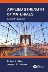
Applied Strength of Materials
Productivity Press (Verlag)
978-1-4987-1675-8 (ISBN)
- Titel erscheint in neuer Auflage
- Artikel merken
Robert L. Mott is professor emeritus of engineering technology at the University of Dayton. He is a member of ASEE, SME, and ASME. He is a Fellow of ASEE and a recipient of the ASEE James H. McGraw Award, Frederick J. Berger Award, and the Archie Higdon Distinguished Educator Award (From Applied Mechanics Division). He is a recipient of the SME Education Award. He holds the Bachelor of Mechanical Engineering degree from General Motors Institute (now Kettering University) and the Master of Science in Mechanical Engineering from Purdue University. His industry experience includes General Motors Corporation, consulting for several companies, and serving as an expert witness on numerous legal cases. He is the author of three textbooks: Applied Fluid Mechanics 7th ed. (co-authored with Joseph A. Untener) and Machine Elements in Mechanical Design 6th ed., published by Pearson/Prentice-Hall; Applied Strength of Materials 6th ed. (co-authored with Joseph A. Untener) with CRC Press. Joseph A. Untener, P.E. is a professor of engineering technology at the University of Dayton. He is a member of ASEE, SME, and ASME. He holds the Bachelor of Mechanical Engineering degree from General Motors Institute (now Kettering University) and the Master of Science in Industrial Administration from Purdue University. He has worked on the design and implementation of manufacturing equipment at General Motors, and served as an engineering consultant for many other companies. He teaches courses in Mechanical Engineering Technology at UD. He has co-authored two textbooks with Robert L. Mott: Applied Fluid Mechanics 7th ed. published by Pearson/Prentice-Hall, and Applied Strength of Materials 6th ed. with CRC Press.
Preface
Basic Concepts in Strength of Materials
The Big Picture
Objective of This Book – To Ensure Safety
Objectives of This Chapter
Problem-solving Procedure
Basic Unit Systems
Relationship Among Mass, Force, and Weight
The Concept of Stress
Direct Normal Stress
Stress Elements for Direct Normal Stresses
The Concept of Strain
Direct Shear Stress
Stress Element for Shear Stresses
Preferred Sizes and Standard Shapes
Experimental and Computational Stress
Design Properties of Materials
The Big Picture
Objectives of This Chapter
Design Properties of Materials
Steel
Cast Iron
Aluminum
Copper, Brass, and Bronze
Zinc, Magnesium, Titanium, and Nickel-Based Alloys
Nonmetals in Engineering Design
Wood
Concrete
Plastics
Composites
Materials Selection
Direct Stress, Deformation, and Design
The Big Picture and Activity
Objectives of this Chapter
Design of Members under Direct Tension or Compression
Design Normal Stresses
Design Factor
Design Approaches and Guidelines for Design Factors
Methods of Computing Design Stress
Elastic Deformation in Tension and Compression Members
Deformation Due to Temperature Changes
Thermal Stress
Members Made of More Than One Material
Stress Concentration Factors for Direct Axial Stresses
Bearing Stress
Design Bearing Stress
Design for Direct Shear, Torsional Shear, and Torsional Deformation
The Big Picture
Objectives of This Chapter
Design for Direct Shear Stress
Torque, Power, and Rotational Speed
Torsional Shear Stress in Members with Circular Cross Sections
Development of the Torsional Shear Stress Formula
Polar Moment of Inertia for Solid Circular Bars
Torsional Shear Stress and Polar Moment of Inertia for Hollow Circular Bars
Design of Circular Members under Torsion
Comparison of Solid and Hollow Circular Members
Stress Concentrations in Torsionally Loaded Members
Twisting – Elastic Torsional Deformation
Torsion in Noncircular Sections
Shearing Forces and Bending Moments in Beams
The Big Picture
Objectives of this Chapter
Beam Loading, Supports, and Types of Beams
Reactions at Supports
Shearing Forces and Bending Moments for Concentrated Loads
Guidelines for Drawing Beam Diagrams for Concentrated Loads
Shearing Forces and Bending Moments for Distributed Loads
General Shapes Found in Bending Moment Diagrams
Shearing Forces and Bending Moments for Cantilever Beams
Beams with Linearly Varying Distributed Loads
Free-Body Diagrams of Parts of Structures
Mathematical Analysis of Beam Diagrams
Continuous Beams – Theorem of Three Moments
Centroids and Moments of Inertia of Areas
The Big Picture
Objectives of This Chapter
The Concept of Centroid – Simple Shapes
Centroid of Complex Shapes
The Concept of Moment of Inertia
Moment of Inertia for Composite Shapes Whose Parts have the Same Centroidal Axis
Moment of Inertia for Composite Shapes – General Case – Use of the Parallel Axis Theorem
Mathematical Definition of Moment of Inertia
Composite Sections Made from Commercially Available Shapes
Moment of Inertia for Shapes with all Rectangular Parts
Radius of Gyration
Section Modulus
Stress Due to Bending
The Big Picture
Objectives of This Chapter
The Flexure Formula
Conditions on the Use of the Flexure Formula
Stress Distribution on a Cross Section of a Beam
Derivation of the Flexure Formula
Applications – Beam Analysis
Applications – Beam Design and Design Stresses
Section Modulus and Design Procedures
Stress Concentrations
Flexural Center or Shear Center
Preferred Shapes for Beam Cross Sections
Design of Beams to be Made from Composite Materials
Shearing Stresses in Beams
The Big Picture
Objectives of this Chapter
Importance of Shearing Stresses in Beams
The General Shear Formula
Distribution of Shearing Stress in Beams
Development of the General Shear Formula
Special Shear Formulas
Design for Shear
Shear Flow
Deflection of Beams
The Big Picture
Objectives of this Chapter
The Need for Considering Beam Deflections
General Principles and Definitions of Terms
Beam Deflections Using the Formula Method
Comparison of the Manner of Support for Beams
Superposition Using Deflection Formulas
Successive Integration Method
Moment-Area Method
Combined Stresses
The Big Picture
Objectives of this Chapter
The Stress Element
Stress Distribution Created by Basic Stresses
Creating the Initial Stress Element
Combined Normal Stresses
Combined Normal and Shear Stresses
Equations for Stresses in Any Direction
Maximum Stresses
Mohr’s Circle for Stress
Stress Condition on Selected Planes
Special Case in which Both Principal Stresses have the Same Sign
Use of Strain-Gage Rosettes to Determine Principal Stress Columns
Columns
The Big Picture
Objectives of this Chapter
Slenderness Ratio
Transition Slenderness Ratio
The Euler Formula for Long Columns
The J. B. Johnson Formula for Short Columns
Summary – Buckling Formulas
Design Factors and Allowable Load
Summary – Method of Analyzing Columns
Column Analysis Spreadsheet
Efficient Shapes for Columns
Specifications of the AISC
Specifications of the Aluminum Association
Non-Centrally Loaded Columns
Pressure Vessels
The Big Picture
Objectives of this Chapter
Distinction Between Thin-Walled and Thick-Walled Pressure Vessels
Thin-Walled Spheres
Thin-Walled Cylinders
Thick-Walled Cylinders and Spheres
Analysis and Design Procedures for Pressure Vessels
Spreadsheet Aid for Analyzing Thick-Walled Spheres and Cylinders
Shearing Stress in Cylinders and Spheres
Other Design Considerations for Pressure Vessels
Composite Pressure Vessels
Connections
The Big Picture
Objectives of this Chapter
Modes of Failure for Bolted Joints
Design of Bolted Connections
Riveted Joints
Eccentrically Loaded Riveted and Bolted Joints
Welded Joints with Concentric Loads
Appendix
Answers to Selected Problems
| Erscheint lt. Verlag | 13.12.2016 |
|---|---|
| Zusatzinfo | 16 page color insert - 17 images, most on one page; 81 Tables, black and white; 17 Illustrations, color; 647 Illustrations, black and white |
| Verlagsort | Portland |
| Sprache | englisch |
| Maße | 203 x 254 mm |
| Gewicht | 2245 g |
| Themenwelt | Technik ► Bauwesen |
| Technik ► Maschinenbau | |
| ISBN-10 | 1-4987-1675-X / 149871675X |
| ISBN-13 | 978-1-4987-1675-8 / 9781498716758 |
| Zustand | Neuware |
| Informationen gemäß Produktsicherheitsverordnung (GPSR) | |
| Haben Sie eine Frage zum Produkt? |
aus dem Bereich
