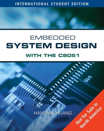
Embedded System Design with C8051
Nelson Engineering (Verlag)
978-0-495-66764-3 (ISBN)
- Titel ist leider vergriffen;
keine Neuauflage - Artikel merken
This book provides a broad and systematic introduction to microcontrollers. Through focusing on the 8051 8-bit microcontroller and its variants, the text aims at helping students learn about modern microcontroller interfacing and applications. For use with design projects, this book also provides numerous more complicated examples to explore the functions and applications of the 8051.
Han-Way Huang is a Professor in the Department of Electrical and Computer Engineering and Technology at Minnesota State University, Mankato. A member of both IEEE and ASEE, he has 25 years of teaching experience in microprocessors and microcontrollers. A well-respected author, he has also written THE HCS12/9S12: AN INTRODUCTION TO HARDWARE AND SOFTWARE (Delmar Learning), EMBEDDED SYSTEM DESIGN WITH M8051 (Cengage Engineering), THE PIC MICROCONTROLLER: AN INTRODUCTION TO SOFTWARE AND INTERFACING (Delmar Learning), THE HC12 MICROCONTROLLER: AN INTRODUCTION (Delmar Learning), and THE HC11 MICROCONTROLLER: AN INTRODUCTION (Delmar Learning). Dr. Huang earned an MS and Ph.D. in Computer Engineering from Iowa State University and the BSEE degree from National Taiwan University.
Chapter 1 Introduction to Microcontroller and the Intel 8051 1.1 Objectives 1.2 Number System Issue 1.2.1 Converting from Binary to Decimal 1.2.2 Converting from Decimal to Binary 1.2.3 Why Octal and Hexadecimal Numbers? 1.2.4 Convert from Binary to Octal 1.2.5 Convert from Octal to Binary 1.2.6 Convert from Binary to Hexadecimal 1.2.7 Convert from Hexadecimal to Binary 1.2.8 Specifying the Number Base 1.3 Binary Addition and Subtraction 1.4 Twos Complement Numbers 1.5 Twos Complement Subtraction 1.6 Overflow 1.7 Representing Nonnumeric Data 1.8 Computer Hardware Organization 1.8.1 The Processor 1.8.2 Microprocessor 1.8.3 Microcontroller 1.8.4 Embedded Systems 1.9 Memory 1.9.1 Magnetic Memory 1.9.2 Optical Memory 1.9.3 Semiconductor Memory 1.9.4 Non-Volatile and Volatile Memory 1.9.5 Random Access Memory 1.9.6 Read-Only Memory 1.10 Memory System Operation 1.10.1 Read Operation 1.10.2 Write Operation 1.11 Program Execution 1.11.1 The Circuit of the Program Counter 1.11.2 Where does the Processor Start to Execute Program? 1.11.3 Instruction Execution Process 1.11.4 Instruction Sequence Example 1.11.5 Instruction Execution Process 1.12 Overview of the 8051 Microcontroller 1.13 The 8051 Memory Space 1.14 The 8051 Registers 1.15 Methods for Addressing Instruction Operands 1.15.1 Implied Register Mode 1.15.2 Direct Register Mode 1.15.3 Immediate Value Mode 1.15.4 Indirect Addressing Mode 1.15.5 Indexed Addressing Mode 1.15.6 Relative Addressing Mode 1.15.7 Absolute Addressing Mode 1.15.8 Long Address Mode 1.15.9 Implied Bit Mode 1.15.10 Direct Bit Mode 1.16 Examples of 8051 Instructions 1.16.1 Data Movement Instructions 1.16.2 The ADD Instructions 1.16.3 The SUB Instructions 1.17 Machine Instruction Timing 1.18 Chapter Summary 1.19 Exercise Problems Chapter 2 8051 Assembly Programming 2.1 Objectives 2.2 What is an Assembly Language Program? 2.2.1 The Label Field 2.2.2 The Operation or Directive Field 2.2.3 The Operand or Argument Field 2.2.4 The Comment Field 2.3 The 8051 Memory Classes 2.4 Assembler Directives 2.4.1 Segments 2.4.2 Location Counter 2.4.3 Directives for Controlling Segments 2.4.4 Directives for Defining Symbols 2.4.5 Directives for Initializing Memory Locations 2.4.6 Directives for Reserving Memory Locations 2.4.7 Directives for Controlling Addresses 2.4.8 Other Directives 2.4.9 Directives for Macro Definitions 2.5 Software Development Issue 2.6 Assembly Program Template 2.7 Writing Programs to Perform Computation 2.7.1 The Carry/Borrow Flag 2.7.2 Multi-Byte Addition 2.7.3 The CY flag and Subtraction 2.7.4 Multi-Byte Subtraction 2.7.5 Multiplication and Division 2.8 Writing Program Loops 2.8.1 The Infinite Loop 2.8.2 The For Loop 2.8.3 The While Loop 2.8.4 The Repeat Until Loop 2.9 Jump Table 2.10 Looping-Support Instructions 2.11 Logical Instructions 2.12 Rotate Instructions 2.13 Boolean Variable Manipulation Instructions 2.14 Hardware and Software Development Tools 2.14.1 Debug Adapter 2.14.2 Demo Boards 2.14.3 Software Tools 2.15 A Using the SiLabs IDE 2.15.1 8051 Program Memory Map 2.15.2 Getting Started with SiLabs IDE 2.15.3 Tool Chain Integration 2.15.4 Creating a New Project 2.15.5 Entering Source Programs 2.15.6 Adding Files to the Project 2.15.7 Building the Project 2.15.8 Downloading the Program for Debugging 2.15.9 Target Build Configuration 2.15.10 Program Execution and Debugging 2.16 Tips for Assembly Program Debugging 2.16.1 Syntax Errors 2.16.2 Logical Errors 2.17 Using Keils ?Vision 2.18 Using the Raisonance RIDE 2.19 Chapter Summary 2.20 Exercise Problems 2.21 Laboratory Exercise Problems and Assignments Chapter 3 Assembly Programming and Simple I/O Operations 3.1 Objectives 3.2 Introduction to I/O Ports 3.3 Original 8051 I/O Port Structures and Operations 3.4 C8051F040 I/O Ports 3.4.1 Pin Assignment and Allocation using the Crossbar Decoder 3.4.2 Configuring the Output Modes of the Port Pins 3.4.3 Port Data Registers 3.4.4 Configuring Port Pins as Digital Inputs 3.4.5 Weak Pullups 3.4.6 Configuring Port 1, 2, and 3 Pins as Analog Inputs 3.4.7 Port 4 through Port 7 3.5 C8051F040 Special Function Registers Paging 3.5.1 Interrupts and SFR Paging 3.6 Simple Output Devices 3.6.1 Interfacing with LEDs 3.6.2 Interfacing with Seven-Segment Displays 3.7 Using Timer 0 to Create Time Delays 3.7.1 Mode 1 of Timer 0 3.7.2 Create Time Delay Using Mode 1 3.8 Simple Input Device 3.9 Using the Digital-to-Analog Converter (DAC) 3.9.1 The AD7302 DAC 3.9.2 Interfacing the AD7302 with the 8051 Variants 3.10 Clock Generation and Control 3.10.1 Internal Oscillator 3.10.2 Using an External Oscillator as the System Clock 3.11 Chapter Summary 3.12 Exercise Problems 3.13 Laboratory Exercise Problems and Assignments Chapter 4 Advanced Assembly Programming 4.1 Objectives 4.2 Introduction 4.3 Stack 4.4 Using the On-Chip XRAM 4.4.1 XRAM of the C8051F040 4.4.2 Two Miscellaneous Operators 4.5 Indexable data structures 4.6 Strings 4.7 Subroutines 4.8 A comparison of Macros and Subroutines 4.9 Issues in Subroutine calls 4.9.1 Parameter Passing 4.9.2 Result returning 4.9.3 Allocation of local variables 4.10 The Stack Frame 4.11 Examples of Subroutine Calls 4.11.1 Multi-precision Division 4.11.2 Signed Divide Operation 4.11.3 Signed Multiplication 4.11.4 Time Delay Subroutine 4.11.5 Bubble Sort 4.11.6 Calculating the Square Root 4.12 Using the UART0 Module to Perform I/O 4.13 A Few More Tips on Assembly Program Debugging 4.13.1 What to Do When the Program Gets Stuck? 4.13.2 General Debugging Strategy 4.14 Chapter Summary 4.15 Exercise Problems 4.16 Lab Exercise Problems and Assignments Chapter 5 C Language Programming 5.1 Objectives 5.2 Introduction to C 5.3 Types, Operators, and Expressions 5.3.1 Data Types 5.3.2 Variable Declarations 5.3.3 Constants 5.3.4 Arithmetic Operators 5.3.5 Bitwise Operators 5.3.6 Relational and Logical Operators 5.3.7 Precedence of Operators 5.4 Control Flow 5.4.1 If Statement 5.4.2 If-Else Statement 5.4.3 Multiway Conditional Statement 5.4.4 Switch Statement 5.4.5 For-Loop Statement 5.4.6 While Statement 5.4.7 Do-While Statement 5.4.8 GOTO Statement 5.5 Input and Output 5.6 Functions and Program Structure 5.6.1 Function Prototype 5.6.2 Writing a C Program with Multiple Functions 5.7 Pointers, Arrays, Structures, and Unions 5.7.1 Pointers and Addresses 5.7.2 Arrays 5.7.3 Pointers and Arrays 5.7.4 Passing Arrays to a Function 5.7.5 Initializing Arrays 5.7.6 Structures 5.7.7 Unions 5.8 Miscellaneous Items 5.8.1 Automatic/External/Static/Volatile 5.8.2 Scope Rules 5.8.3 Type Casting 5.9 Using the C Compiler 5.10 C Language Extensions for the 8051 MCU 5.10.1 Memory Model 5.10.2 Storage Class Language Extensions 5.10.3 Pointers 5.10.4 Generic Pointers 5.10.5 Memory-Specific Pointers 5.10.6 Absolute Variable Location 5.10.7 Parameters and Local Variables 5.10.8 Passing Parameters in Registers 5.10.9 Function Return Values 5.10.10 Function Declaration 5.10.11 Specifying Register Bank for a Function 5.10.12 In-Line Assembly Instructions 5.10.13 Header Files 5.11 C Library Functions 5.12 Using SiLabs IDE to Develop C Programs 5.13 Building Multiple File Projects 5.14 Using UART C functions 5.15 Tips for Debugging C Programs 5.16 Chapter Summary 5.17 Exercise Problems 5.18 Laboratory Exercise Problems and Assignments Chapter 6 Interrupts and Resets 6.1 Objectives 6.2 Fundamental Concepts of Interrupts 6.2.1 What is an Interrupt? 6.2.2 Why are Interrupts Used? 6.2.3 Enabling and Disabling Interrupts 6.2.4 Handling Multiple Interrupts by Prioritizing them 6.2.5 Servicing the Interrupt 6.2.6 What is an Interrupt Vector? 6.2.7 How to Write an Interrupt-Driven Program? 6.3 Resets 6.4 The 8051 Interrupts 6.4.1 The 8051 Interrupt Priority Structure 6.4.2 INT0 and INT1 Pins Interrupts 6.4.3 External Interrupts 6.5 The 8051 Reset 6.5.1 The RST Pin Reset 6.5.2 Power-On Reset 6.5.3 Power Failure Reset 6.5.4 JTAG Debug Reset 6.5.5 Missing Clock Detector (MCD) Reset 6.5.6 Comparator 0 Reset 6.5.7 External CNVSTR0 Pin Reset 6.5.8 Watchdog Timer Reset 6.6 Power-Saving Modes of Operation 6.6.1 The IDLE Mode 6.6.2 The STOP Mode 6.7 Chapter Summary 6.8 Exercise Problems 6.9 Lab Exercise Problems and Assignments Chapter 7 Advanced Parallel I/O 7.1 Objectives 7.2 Electrical Characteristic Considerations for I/O Interfacing 7.2.1 Voltage-Level Compatibility 7.2.2 Current Drive Capability 7.2.3 Timing Compatibility 7.3 Liquid Crystal Displays (LCD) 7.4 The HD44780U LCD Controller 7.4.1 Display Data RAM 7.4.2 Character Generator ROM (CGROM) 7.4.3 Character Generator RAM (CGRAM) 7.4.4 Registers 7.4.5 Instruction Description 7.4.6 Interfacing the HD44780U to the 8051 Microcontroller 7.5 Using Keypad as an Input Device 7.5.1 How to Perform Scanning Keypad 7.5.2 How to Perform Keypad Debouncing 7.5.3 ASCII Code Lookup 7.6 Driving Stepper Motor 7.6.1 Stepper Motor Drivers 7.7 Chapter Summary 7.8 Exercise Problems 7.9 Lab Exercise Problems and Assignments Chapter 8 Timers and Programmer Counter Array 8.1 Objectives 8.2 Introduction 8.3 Timer 0 and Timer 1 8.3.1 Mode 0: 13-bit Counter/Timer 8.3.2 Mode 1: 16-bit Counter/Timer 8.3.3 Mode 2: 8-bit Counter/Timer with Auto-Reload 8.3.4 Mode 3: Two 8-bit Counter/Timers (Timer 0 only) 8.3.5 Applications of Timer 0 and Timer 1 8.4 Timer 2, Timer 3, and Timer 4 8.4.1 Configuring Timer 2, 3, and 4 to Count Down 8.4.2 Timer 2, 3, or 4 Capture Mode 8.4.3 Timer 2, 3, and 4 Auto-Reload Mode (Up or Down Counter) 8.4.4 Toggle (Programmable) Clock Out Mode 8.4.5 Timer 2 Baud Rate Generation Mode 8.4.6 Applications of Timer 2 8.5 Programmable Counter Array 8.5.1 PCA Timer/Counter 8.5.2 Capture/Compare Modules 8.5.3 Edge-triggered Capture Mode 8.5.4 16-bit Software Timer and High Speed Output (Toggle) 8.5.5 C8051F040 PCA Frequency Output Mode 8.5.6 8-bit Pulse Width Modulation Mode (Fixed Frequency) 8.5.7 16-bit Pulse Width Modulator Mode (Fixed Frequency) 8.6 DC Motor Control 8.6.1 DC Motor Driver IC 8.6.2 Driving a DC Motor Using the SN754410 8.7 CHAPTER SUMMARY 8.8 Exercise Problems 8.9 Lab Exercise Problems and Assignments Chapter 9 Universal Asynchronous Receiver Transceiver (UART) 9.1 Objectives 9.2 Concepts of Serial I/O 9.3 The RS-232 Standard 9.3.1 EIA-232 Electrical Specification 9.3.2 EIA-232 Functional Specification 9.3.3 EIA-232 Mechanical Specification 9.3.4 EIA-232 Procedural Specification 9.3.5 Data Format 9.3.6 UART detectable Errors 9.3.7 Null Modem Connection 9.4 The 8051 UART module 9.4.1 UART Pins 9.4.2 UART Operation Mode 9.4.3 Registers Associated to UART 9.4.4 Baud Rate Generation for the Original 8051 9.4.5 Baud Rate Generation for the C8051F040 UART Modules 9.5 The Operation of UART Module 9.5.1 UART Mode 0 9.5.2 UART Mode 1 9.5.3 UART Mode 2 9.5.4 UART Mode 3 9.6 Applications of UART Mode 0 9.7 Applications of UART Mode 1 9.7.1 Direct Connection of UART in Mode 1 9.7.2 Data Exchange with UART Mode 1 via EIA232 Interface 9.8 Applications of UART Mode 2 and 3 9.8.1 Multiprocessor Application of UART of the Original 8051 9.8.2 Multiprocessor Application of UART of C8051F040 9.9 Chapter Summary 9.10 Exercise Problems 9.11 Lab Exercise Problems and Assignments Chapter 10 Serial Peripheral Interface 10.1 Objectives 10.2 Introduction to the SPI Function 10.3 SPI Signal Pins 10.4 Registers Related to SPI 10.5 SPI Operation 10.5.1 Transmission Formats 10.5.2 SPI Master Mode Operation 10.5.3 SPI Slave Mode Operation 10.5.4 SPI Baud Rate 10.6 SPI Interrupt Sources 10.7 SPI Circuit Connection 10.8 SPI-Compatible Chips 10.9 The 74LV595 Shift Register 10.10 The LTC1661 D/A Converter 10.10.1 Signal pins 10.10.2 Data Format 10.10.3 DAC Control Functions 10.10.4 LTC1661 Output Voltage 10.10.5 Interfacing the LTC1661 with the C8051F040 10.11 EEPROM with SPI Interface 10.11.1 The 25AA080A EEPROM 10.11.2 Read Operation 10.11.3 Write Operation 10.11.4 Write Status Register 10.11.5 Data Protection 10.11.6 Interfacing the 25AA080A with the C8051F040 10.12 Matrix LED Displays 10.12.1 The Organization of Matrix LED Displays 10.12.2 Colors of Matrix LED Displays 10.12.3 Connection Method 10.12.4 Dimension of Matrix LED Displays 10.12.5 Method of Driving Matrix LED Displays 10.13 The MAX6952 Matrix LED Display Driver 10.12.1 Pin Functions 10.12.2 Internal Registers 10.12.3 Blinking Operation 10.12.4 Choosing Values for RSET and CSET 10.14 Chapter Summary 10.15 Exercise Problems 10.16 Lab Exercise Problems and Assignments Chapter 11 System Management Bus/Inter-Integrated Circuit (I2C) 11.1 Objectives 11.2 Overview of Protocols 11.2.1 Overview of I2C 11.2.2 Overview of SMBus 11.2.3 Differences between I2C and SMBus protocols 11.3 I2C and SMB Protocols 11.3.1 Communication Procedure of I2C and SMBus 11.3.2 Signal Levels 11.3.3 I2C and SMBus Data Transfer Signal Components 11.3.4 Bus Arbitration 11.3.5 Synchronization 11.3.6 Data Transfer Format 11.4 The SMBus of the C8051F040 11.4.1 The SMB0CN Control Register 11.4.2 The SMB0CR register 11.4.3 SMBus Data Register (SMB0DAT) 11.4.4 Address Register 11.4.5 Status Register 11.5 Using the C8051F040 SMBus 11.5.1 Implementation Choices 11.5.2 Interfacing the Serial EEPROM 24LC08 with SMBus 11.6 The Digital Thermometer and Thermostat DS1631A 11.6.1 Pin Assignment 11.6.2 Functional Description 11.6.3 DS1631A Registers 11.6.4 The DS1631A Operation 11.6.5 DS1631A Command Set 11.6.6 Interfacing the DS1631A with the C8051F040 11.7 Interfacing with I2C Serial Real-Time Clock DS1337 11.7.1 Signal Functions 11.7.2 Address Map 11.7.3 Clock and Calendar 11.7.4 Special Registers 11.7.5 Alarms 11.7.6 Interfacing the DS1337 with C8051F040 11.8 Chapter Summary 11.9 Exercise Problems 11.10 Laboratory Exercise Problems and Assignments Chapter 12 Analog to Digital and Digital to Analog Converters 12.1 Objectives 12.2 Basics of A/D Conversion 12.2.1 A Data Acquisition System 12.2.2 Analog Voltage and Digital Code Characteristics 12.2.3 A/D Conversion Algorithms 12.2.4 Optimal Voltage Range for A/D Conversion 12.2.5 Scaling Circuit 12.2.6 Voltage Translation Circuit 12.3 The C8051F040 A/D Converters 12.4 The 12-bit ADC0 A/D Converter 12.4.1 Analog Multiplexer and Programmable Gain Amplifier 12.4.2 Dedicated External Analog Inputs 12.4.3 High Voltage Difference Amplifier (HVDA) 12.4.4 Additional Analog Input from Port 3 12.4.5 Analog Multiplexer Channel Selection 12.4.6 Programmable Gain Amplifier (PGA) 12.4.7 A/D Conversion Clock 12.4.8 A/D Conversion Start Methods 12.4.9 Analog Input Signal Tracking (Sampling) 12.4.10 A/D Voltage Reference 12.4.11 Interpreting the Conversion Result 12.4.12 ADC0 Programmable Window Detector 12.4.13 On-Chip Temperature Sensor 12.5 The 8-bit ADC2 A/D Converter 12.5.1 Analog Multiplexer and PGA 12.5.2 ADC2 Operation 12.5.3 Tracking Modes 12.5.4 ADC2 Programmable Window Detector 12.6 Using the temperature sensor TC1047A 12.7 Measuring Barometric Pressure 12.8 Measuring Humidity 12.9 Digital-to-Analog Converter of the C8051F040 12.9.1 Signal Pins Related to DACs 12.9.2 Registers Related to DACs 12.9.3 DAC Operation 12.10 Chapter Summary 12.11 Exercise Problems 12.12 Lab Exercise Problems and Assignment Chapter 13 Controller Area Network (CAN) 13.1 Objectives 13.2 Overview of the Controller Area Network 13.2.1 Layered Approach in CAN 13.2.2 General Characteristic of CAN 13.3 CAN Messages 13.3.1 Data Frame 13.3.2 Remote Frame 13.3.3 Error Frame 13.3.4 Overload Frame 13.3.5 Interframe Space 13.3.6 Message Filtering 13.3.7 Message Validation 13.3.8 Bitstream Encoding 13.4 Error Handling 13.4.1 Bit Error 13.4.2 Stuff Error 13.4.3 CRC Error 13.4.4 Form Error 13.4.5 Acknowledgement Error 13.4.6 Error Signaling 13.5 Fault Confinement 13.5.1 CAN Node Status 13.5.2 Error Counts 13.6 CAN Message Timing 13.6.1 Nominal Bit Time 13.6.2 Length of Time Segments 13.7 Synchronization Issue 13.7.1 Resynchronization Jump Width 13.7.2 Phase Error of an Edge 13.8 The C8051F040 CAN Module 13.8.1 The Structure of the CAN Controller 13.8.2 Registers Related to CAN Module 13.8.3 CAN0ADR Autoincrementing Features 13.8.4 The CAN Core Registers 13.8.5 Message Interface Register Sets IF1 and IF2 13.8.6 Message Handling Registers 13.8.7 Message Objects in the Message Memory 13.9 CAN Operation Modes 13.9.1 Normal Mode 13.9.2 Basic Mode 13.9.3 Test Mode 13.9.4 Silent Mode 13.9.5 Loop Back Mode 13.9.6 Loop Back Combined with Silent Mode 13.10 Can Module Operation 13.10.1 Managing Message Objects 13.10.2 Data Transfer to/from Message RAM 13.10.3 Transmission of Messages 13.10.4 Acceptance Filtering of Received Messages 13.10.5 Reception of Data Frame 13.10.6 Reception of Remote Frame 13.10.7 Receive/Transmit Priority 13.11 Configuration of Message Objects 13.11.1 Configuration of a Message Objects to be Transmitted 13.11.2 Updating a Transmit Object 13.11.3 Configuration of a Receive Object 13.12 Handling of Received Messages 13.13 Configuration of a FIFO Buffer 13.14 Handling of CAN Interrupts 13.15 Setting the CAN Bit Timing Parameters 13.16 Physical CAN Bus Connection 13.16.1 The SN65HVD230 CAN Bus Transceiver 13.16.2 Interfacing the SN65HVD230 to the C8051F040 13.17 Applications of the C8051F040 CAN Module 13.18 Chapter Summary 13.19 Exercise Problems 13.20 Laboratory Exercise Problems and Assignments Chapter 14 Memory Subsystem 14.1 Objectives 14.2 Introduction 14.3 Basic Concepts of Bus 14.4 Waveforms of Bus Signals 14.5 Bus Transactions 14.6 Bus Multiplexing 14.7 The C8051F040 Flash Program Memory 14.7.1 Programming the Flash Memory 14.7.2 Non-Volatile Data Storage 14.7.3 Security Options 14.8 External Data Memory Interface and On-Chip XRAM 14.9 Configuring the External Memory Interface 14.9.1 Port Selection and Configuration 14.9.2 Multiplexed and Non-Multiplexed Selection 14.9.3 Memory Mode Selection 14.9.4 Timing 14.10 Issues Related to Adding External Memory 14.10.1 Memory Space Assignment 14.10.2 Address Decoder Design 14.10.3 Timing Verification 14.11 Memory Devices 14.11.1 The CY7C1399BN SRAM 14.11.2 AT28BV256 EEPROM 14.12 Example of External Memory Expansion for the C8051F040 14.12.1 Memory Space Assignment 14.12.2 Address Latch 14.12.3 Address Decoder Design 14.12.4 Timing Verification 14.13 Chapter Summary 14.14 Exercise Problems 14.15 Lab Exercise Problems and Assignments Appendix A. 8051 Instruction Execution Times Appendix B. Tutorial for Using the Keils ?Vision IDE Appendix C. Tutorial for Using the Raisonances Ride IDE Appendix D. C8051F040 Special Function Registers Appendix E. C8051F040 SFR PAGE Definition (Keil and Raisonance) Appendix F. Procedure for Setting up HyperTerminal Appendix G. Keil C Library Functions Appendix H. Keil C Library Function Prototypes Appendix I. Music Note Frequencies References Glossary Index
| Erscheint lt. Verlag | 4.1.2009 |
|---|---|
| Zusatzinfo | Illustrations |
| Verlagsort | Florence, KY |
| Sprache | englisch |
| Maße | 185 x 231 mm |
| Gewicht | 1226 g |
| Themenwelt | Technik ► Elektrotechnik / Energietechnik |
| ISBN-10 | 0-495-66764-1 / 0495667641 |
| ISBN-13 | 978-0-495-66764-3 / 9780495667643 |
| Zustand | Neuware |
| Haben Sie eine Frage zum Produkt? |
aus dem Bereich


