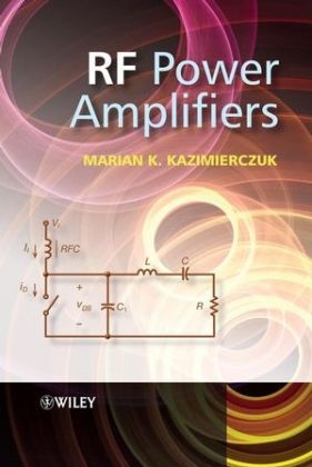
RF Power Amplifiers
Wiley-Blackwell (Verlag)
978-0-470-77946-0 (ISBN)
- Titel erscheint in neuer Auflage
- Artikel merken
An advanced textbook covering the fundamental theory of RF power amplifiers and their uses, this book provides essential guidance for design procedures. The introduction explains the basic theory of RF power amplifiers besides providing the basic classification of the different types of RF power amplifier. It then systematically dedicates a chapter to each different of RF power amplifier covering A, B and C, D (full-bridge and half-bridge types), E (zero-voltage-switching and zero-current-switching), F and DE amplifiers. Throughout this comprehensive guide, the optimal operating conditions are explored and the possible causes for suboptimum operation explained. The book then considers integrated inductors and linearization techniques and LC Oscillators in the concluding chapters. A comprehensive text covering the fundamentals of RF power amplifiers and their range of applications in radio and TV broadcasting, wireless communications and radars. Presents accessible coverage of the complex principles of operation of RF power amplifiers and radio power systems. Introduces the fundamental design techniques and procedures for practitioners for RF power amplifiers.
All chapters contain examples and design procedures throughout, with review questions and problems at the end of each chapter. A solutions manual is available for instructors upon enquiry
Marian K. Kazimierczuk is Professor of Electrical engineering at Wright State University, Dayton, Ohio, USA. He is the author of five books, over 130 journal papers, over 150 conference papers, and seven patents. he is a fellow of the IEE and he received an Outstanding Teacher Award from the American Society for Engineering Education in 2008. His research interests are in the areas of RF power amplifiers, radio transmitters, power electronics, PWM dc-dc power converters, resonant dc-dc power converters, modeling and controls, semiconductor power devices, magnetic devices, and renewable energy sources.
Preface About the Author List of Symbols 1. Introduction 1.1 Block Diagram of RF Power Amplifiers 1.2 Classes of Operation of RF Power Amplifiers 1.3 Parameters of RF Power Amplifiers 1.4 Conditions for 100% Efficiency of Power Amplifiers 1.5 Conditions for Nonzero Output Power at 100% Efficiency of Power Amplifiers 1.6 Output Power of Class E ZVS Amplifier 1.7 Class E ZCS Amplifier 1.8 Propagation of Electromagnetic Waves 1.9 Frequency Spectrum 1.10 Duplexing 1.11 Multiple-access Techniques 1.12 Nonlinear Distortion in Transmitters 1.13 Harmonics of Carrier Frequency 1.14 Intermodulation 1.15 Dynamic Range of Power Amplifiers 1.16 Analog Modulation 1.17 Digital Modulation 1.18 Radars 1.19 Radio-frequency Identification 1.20 Summary 1.21 References 1.22 Review Questions 1.23 Problems 2. Class A RF Power Amplifier 2.1 Introduction 2.2 Circuit of Class A RF Power Amplifier 2.3 Power MOSFET Characteristics 2.4 Waveforms of Class A RF Amplifier 2.5 Parameters of Class A RF Power Amplifier 2.6 Parallel-resonant Circuit 2.7 Power Losses and Efficiency of Parallel Resonant Circuit 2.8 Impedance Matching Circuits 2.9 Class A RF Linear Amplifier 2.10 Summary 2.11 References 2.12 Review Questions 2.13 Problems 3. Class AB, B, and C RF Power Amplifiers 3.1 Introduction 3.2 Class B RF Power Amplifier 3.3 Class AB and C RF Power Amplifiers 3.4 Push-pull Complementary Class AB, B, and C RF Power Amplifiers 3.5 Transformer-coupled Class B Push-pull Amplifier 3.6 Class AB, B, and C Amplifiers of Variable-envelope Signals 3.7 Summary 3.8 References 3.9 Review Questions 3.10 Problems 4. Class D RF Power Amplifier 4.1 Introduction 4.2 Circuit Description 4.3 Principle of Operation 4.4 Topologies of Class D Voltage-source RF Power Amplifiers 4.5 Analysis 4.6 Voltage Transfer Function 4.7 Bandwidth of Class D Amplifier 4.8 Efficiency of Half-bridge Class D Power Amplifier 4.9 Design Example 4.10 Class D RF Power Amplifier with Amplitude Modulation 4.11 Transformer-coupled Push-pull Class D Voltage-switching RF Power Amplifier 4.12 Class D Full-bridge RF Power Amplifier 4.13 Phase Control of Full-bridge Class D Power Amplifier 4.14 Class D Current-switching RF Power Amplifier 4.15 Transformer-coupled Push-pull Class D Current-switching RF Power Amplifier 4.16 Bridge Class D Current-switching RF Power Amplifier 4.17 Summary 4.18 References 4.19 Review Questions 4.20 Problems 5. Class E RF Zero-voltage-switching RF Power Amplifier 5.1 Introduction 5.2 Circuit Description 5.3 Circuit Operation 5.4 ZVS and ZDS Operation of Class E Amplifier 5.5 Suboptimum Operation 5.6 Analysis 5.7 Maximum Operating Frequency 5.8 Choke Inductance 5.9 Summary of Parameters at D = 0 . 5 5.10 Efficiency 5.11 Design of Basic Class E Amplifier 5.12 Impedance Matching Resonant Circuits 5.13 Push-pull Class E ZVS RF Amplifier 5.14 Class E ZVS RF Power Amplifier with Finite DC-feed Inductance 5.15 Class E ZVS Amplifier with Parallel-series Resonant Circuit 5.16 Class E ZVS Amplifier with Nonsinusoidal Output Voltage 5.17 Class E ZVS Power Amplifier with Parallel Resonant Circuit 5.18 Amplitude Modulation of Class E ZVS RF Power Amplifier 5.19 Summary 5.20 References 5.21 Review Questions 5.22 Problems 6. Class E Zero-current-switching RF Power Amplifier 6.1 Introduction 6.2 Circuit Description 6.3 Principle of Operation 6.4 Analysis 6.5 Power Relationships 6.6 Element Values of Load Network 6.7 Design Example 6.8 Summary 6.9 References 6.10 Review Questions 6.11 Problems 7. Class DE RF Power Amplifier 7.1 Introduction 7.2 Analysis of Class DE RF Power Amplifier 7.3 Components 7.4 Device Stresses 7.5 Design Equations 7.6 Maximum Operating Frequency 7.7 Class DE Amplifier with Only One Shunt Capacitor 7.8 Components 7.9 Cancellation of Nonlinearities of Transistor Output Capacitances 7.10 Summary 7.11 References 7.12 Review Questions 7.13 Problems 8. Class F RF Power Amplifier 8.1 Introduction 8.2 Class F RF Power Amplifier with Third Harmonic 8.3 Class F RF Power Amplifier with Third and Fifth Harmonics 8.4 Class F RF Power Amplifier with Third, Fifth, and Seventh Harmonics 8.5 Class F RF Power Amplifier with Parallel-resonant Circuit and Quarter-wavelength Transmission Line 8.6 Class F RF Power Amplifier with Second Harmonic 8.7 Class F RF Power Amplifier with Second and Fourth Harmonics 8.8 Class F RF Power Amplifier with Second, Fourth, and Sixth Harmonics 8.9 Class F RF Power Amplifier with Series-resonant Circuit and Quarter-wavelength Transmission Line 8.10 Summary 8.11 References 8.12 Review Questions 8.13 Problems 9. Linearization and Efficiency Improvement of RF Power Amplifiers 9.1 Introduction 9.2 Predistortion 9.3 Feedforward Linearization Technique 9.4 Negative Feedback Linearization Technique 9.5 Envelope Elimination and Restoration 9.6 Envelope Tracking 9.7 The Doherty Amplifier 9.8 Outphasing Power Amplifier 9.9 Summary 9.10 References 9.11 Review Questions 9.12 Problems 10. Integrated Inductors 10.1 Introduction 10.2 Skin Effect 10.3 Resistance of Rectangular Trace 10.4 Inductance of Straight Rectangular Trace 10.5 Meander Inductors 10.6 Inductance of Straight Round Conductor 10.7 Inductance of Circular Round Wire Loop 10.8 Inductance of Two-parallel Wire Loop 10.9 Inductance of Rectangle of Round Wire 10.10 Inductance of Polygon Round Wire Loop 10.11 Bondwire Inductors 10.12 Single-turn Planar Inductors 10.13 Inductance of Planar Square Loop 10.14 Planar Spiral Inductors 10.15 Multimetal Spiral Inductors 10.16 Planar Transformers 10.17 MEMS Inductors 10.18 Inductance of Coaxial Cable 10.19 Inductance of Two-wire Transmission Line 10.20 Eddy Currents in Integrated Inductors 10.21 Model of RF Integrated Inductors 10.22 PCB Integrated Inductors 10.23 Summary 10.24 References 10.25 Review Questions 10.26 Problems Appendices Appendix A SPICE Model of Power MOSFETs Appendix B Introduction to SPICE Appendix C Introduction to MATLAB Answers to Problems Index
| Erscheint lt. Verlag | 1.12.2008 |
|---|---|
| Zusatzinfo | Illustrations |
| Verlagsort | Hoboken |
| Sprache | englisch |
| Maße | 174 x 254 mm |
| Gewicht | 874 g |
| Einbandart | gebunden |
| Themenwelt | Technik ► Elektrotechnik / Energietechnik |
| Technik ► Nachrichtentechnik | |
| ISBN-10 | 0-470-77946-2 / 0470779462 |
| ISBN-13 | 978-0-470-77946-0 / 9780470779460 |
| Zustand | Neuware |
| Haben Sie eine Frage zum Produkt? |
aus dem Bereich
