Interpreting Engineering Drawings
Delmar Cengage Learning (Verlag)
978-1-4180-5573-8 (ISBN)
- Titel erscheint in neuer Auflage
- Artikel merken
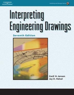
Comprehensive, state-of-the-art training is the cornerstone of this popular guide that shows users how to create professional-quality engineering drawings that can be interpreted with precision in today's technology-based industries. Clearly the most flexible, user-friendly book of its kind on the market, the seventh edition offers unsurpassed coverage of the theory and practical applications individuals need to communicate technical concepts in an international marketplace. All material is developed around the latest ASME drawing standards, helping readers keep pace with the dynamic changes in the field of engineering graphics.
Jay D. Helsel has worked more than 35 years in education, having served as a professor of applied engineering and technology courses, chairperson of the Department of Applied Engineering and Technology, and Vice President for Administration and Finance at California University of Pennsylvania. Dr. Helsel has had extensive experience teaching mechanical drafting at both the secondary and post-secondary levels and has worked in industry as well. He holds an undergraduate degree from California University of Pennsylvania, a master's degree from the Pennsylvania State University, and a doctoral degree from the University of Pittsburgh. Dr. Helsel is now a full-time writer and has authored publications such as Engineering Drawing and Design, Fundamentals of Engineering Drawing, Programmed Blueprint Reading, Computer-Aided Engineering Drawing, and Mechanical Drawing: Board and CAD Techniques, as well as various workbooks and other ancillary products associated with the above publications. Cecil H. Jensen took an early retirement from teaching to devote his full time to technical writing. He held the position of Technical Director at the McLaughlin Collegiate and Vocational Institute, Oshawa, Ontario, Canada, and has more than twenty-seven years of teaching experience in mechanical drafting. He was an active member of the Canadian Standards Association (CSA) Committee on Technical Drawings. Mr. Jensen has represented Canada at international (ISO) conferences on engineering drawing standards, which took place in Oslo, Norway and Paris, France. He also represented Canada on the ANSI Y14.5M Committee on Dimensioning and Tolerancing. He is the successful author of numerous texts including Engineering Drawing and Design, Fundamentals of Engineering Drawing, Geometric Dimensioning and Tolerancing for Engineering and Manufacturing Technology, Computer-Aided Engineering Drawing, and Home Planning and Design. Before he began teaching, Mr. Jensen spent several years in industrial design. He also supervised the evening courses in Oshawa and was responsible for teaching selected courses for General Motors Corporation apprentices.
Unit 1
Bases for Interpreting Engineering Drawings
Engineering Drawings
Line Styles and Lettering
Sketching
Information Shown on Assignment Drawings
Unit 2
Lines Used to Describe the Shape of a Part
Title Blocks and Title Strips
Drawing to Scale
Unit 3
Circular Features
Center Lines
Sketching Circles and Arcs
Unit 4
Working Drawings
Arrangement of Views
Third-Angle Projection
Sketching Views in Third-Angle Projection
Unit 5
Dimensioning
Dimensioning Straight-Line Features
Unit 6
Inclined Surfaces
Measurement of Angles
Symmetrical Outlines
Machine Slots
Unit 7
Pictorial Sketching
Isometric Sketching
Oblique Sketching
Unit 8
Machining Symbols
Not-To-Scale Dimensions
Drawing Revisions
Break Lines
Unit 9
Sectional Views
Types of Sections
Countersinks, Counterbores, and Spotfaces
Intersection of Unfinished Surfaces
Unit 10
Chamfers
Undercuts
Tapers
Knurls
Unit 11
One- and Two-View Drawings
Multiple-Detail Drawings
Functional Drafting
Unit 12
Surface Texture
Surface Texture Symbol
Surface Texture Ratings
Control Requirements
Unit 13
Tolerances and Allowances
Definitions
Tolerancing Methods
Unit 14
Inch Fits
Description of Fits
Standard Inch Fits
Unit 15 Metric Fits
Unit 16
Threaded Fasteners
Threaded Assemblies
Threaded Holes
Inch Threads
Right- and Left-Handed Threads
Metric Threads
Unit 17 Revolved and Removed Sections
Unit 18
Keys
Set Screws
Flats
Bosses and Pads
Dimension Origin Symbol
Rectangular Coordinate Dimensioning Without Dimension Lines
Rectangular Coordinate Dimensioning in Tabular Form
Unit 19 Oblique Surfaces
Unit 20 Primary Auxiliary Views
Unit 21 Secondary Auxiliary Views
Unit 22
Development Drawings
Joints, Seams, and Edges
Sheet Metal Sizes
Stampings
Unit 23 Arrangement of Views
Unit 24
Piping
Piping Drawings
Pipe Drawing Symbols
Unit 25 Bearings
Unit 26
Manufacturing Materials
Cast Iron
Steel
Plastics
Rubber
Unit 27
Casting Processes
Casting Design
Cored Castings
Machining Lugs
Surface Coatings
Unit 28
Chain Dimensioning
Base Line (Datum) Dimensioning
Unit 29
Alignment of Parts and Holes
Partial Views
Naming of Views for Spark Adjuster
Drill Sizes
Unit 30
Broken-Out and Partial Sections
Webs in Section
Ribs in Section
Spokes in Section
Unit 31
Pin Fasteners
Sections Through Shafts, Pins, and Keys
Arrangement of Views of Drawing A-85M
Unit 32
Drawings for Numerical Control
Dimensioning for Numerical Control
Dimensioning for Two-Axis Coordinate System
Unit 33
Assembly Drawings
Bill of Material (Item List)
Helical Springs
Unit 34
Structural Steel Shapes
Phantom Outlines
Conical Washers
Unit 35
Welding Drawings
Welding Symbols
Fillet Welds
Unit 36
Groove Welds
Supplementary Symbols
Unit 37
Other Basic Welds
Plug and Slot Welds
Unit 38 Gears, Spur Gears
Unit 39 Bevel Gears
Unit 40 Gear Trains
Unit 41 Cams
Unit 42
Antifriction Bearings
Retaining Rings
O-Ring Seals
Clutches
Belt Drives
Unit 43 Ratchet Wheels
Unit 44
Modern Engineering Tolerancing
Geometric Tolerancing
Feature Control Frame
Form Tolerances
Straightness
Unit 45
Straightness of a Feature Size
Feature of Size Definitions
Material Condition Symbols
Maximum Material Condition (MMC)
Regardless of Feature Size (RFS)
Least Material Condition (LMC)
Straightness of a Feature of Size
Unit 46
Form Tolerances
Flatness
Circularity
Cylindricity
Unit 47
Datums and the Three-Plane Concept
Datums for Geometric Tolerancing
Three-Plane System
Uneven Surfaces
Datum Feature Symbol
Unit 48
Orientation Tolerances
Orientation Tolerancing for Flat Surfaces
Unit 49
Orientation Tolerancing for Features of Size
Internal Cylindrical Features
External Cylindrical Features
Unit 50 Datum Targets
Unit 51 Tolerancing of Features by Position
Tolerancing Methods
Coordinate Tolerancing
Advantages of Coordinate Tolerancing
Disadvantages of Coordinate Tolerancing
Positional Tolerancing
Material Condition Basis
Positional Tolerancing for Circular Features
Advantages of Positional Tolerancing
Unit 52 Selection of Datum Features for Positional Tolerancing
Unit 53
Profile Tolerances
Profile of a Line
Profile of a Surface
Unit 54 Runout Tolerances
Circular Runout
Total Runout
Establishing Datums
| Erscheint lt. Verlag | 27.9.2006 |
|---|---|
| Verlagsort | Clifton Park |
| Sprache | englisch |
| Maße | 217 x 279 mm |
| Gewicht | 1095 g |
| Themenwelt | Technik |
| ISBN-10 | 1-4180-5573-5 / 1418055735 |
| ISBN-13 | 978-1-4180-5573-8 / 9781418055738 |
| Zustand | Neuware |
| Informationen gemäß Produktsicherheitsverordnung (GPSR) | |
| Haben Sie eine Frage zum Produkt? |
aus dem Bereich


