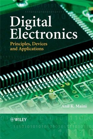
Digital Electronics
John Wiley & Sons Inc (Verlag)
978-0-470-03214-5 (ISBN)
The fundamentals and implementation of digital electronics are essential to understanding the design and working of consumer/industrial electronics, communications, embedded systems, computers, security and military equipment. Devices used in applications such as these are constantly decreasing in size and employing more complex technology. It is therefore essential for engineers and students to understand the fundamentals, implementation and application principles of digital electronics, devices and integrated circuits. This is so that they can use the most appropriate and effective technique to suit their technical need.
This book provides practical and comprehensive coverage of digital electronics, bringing together information on fundamental theory, operational aspects and potential applications. With worked problems, examples, and review questions for each chapter, Digital Electronics includes:
information on number systems, binary codes, digital arithmetic, logic gates and families, and Boolean algebra;
an in-depth look at multiplexers, de-multiplexers, devices for arithmetic operations, flip-flops and related devices, counters and registers, and data conversion circuits;
up-to-date coverage of recent application fields, such as programmable logic devices, microprocessors, microcontrollers, digital troubleshooting and digital instrumentation.
A comprehensive, must-read book on digital electronics for senior undergraduate and graduate students of electrical, electronics and computer engineering, and a valuable reference book for professionals and researchers.
Anil K. Mainiis a senior scientist and Associate Director at Laser Science and Technology Centre, an R&D establishment under Defence Research and Development Organization (DRDO), India. He has worked on a wide range of electronics and optoelectronic laser systems. His areas of expertise include Optoelectronic sensor systems, Laser systems, Power electronics, Digital electronics and related technologies. He has eight books to his credit including Satellite Technology: Principles and Applications, Microwaves and Radar, Handbook of Electronics, Electronics and Communication Simplified, Electronics for Competitions, Television Technician’s Course, Electronics Projects for Beginners and Facing the Interview Board for Electronics Professionals. He has also authored about 150 technical articles and papers in national and international magazines and conferences and has two patents (Patent pending) to his credit. He is Life Fellow of Institution of Electronics and Telecommunication Engineers (IETE) and Life Member of Indian Laser Association
Preface xxi
1 Number Systems 1
1.1 Analogue Versus Digital 1
1.2 Introduction to Number Systems 2
1.3 Decimal Number System 2
1.4 Binary Number System 3
1.4.1 Advantages 3
1.5 Octal Number System 4
1.6 Hexadecimal Number System 4
1.7 Number Systems – Some Common Terms 4
1.7.1 Binary Number System 4
1.7.2 Decimal Number System 5
1.7.3 Octal Number System 5
1.7.4 Hexadecimal Number System 5
1.8 Number Representation in Binary 5
1.8.1 Sign-Bit Magnitude 5
1.8.2 1’s Complement 6
1.8.3 2’s Complement 6
1.9 Finding the Decimal Equivalent 6
1.9.1 Binary-to-Decimal Conversion 6
1.9.2 Octal-to-Decimal Conversion 6
1.9.3 Hexadecimal-to-Decimal Conversion 7
1.10 Decimal-to-Binary Conversion 7
1.11 Decimal-to-Octal Conversion 8
1.12 Decimal-to-Hexadecimal Conversion 9
1.13 Binary–Octal and Octal–Binary Conversions 9
1.14 Hex–Binary and Binary–Hex Conversions 10
1.15 Hex–Octal and Octal–Hex Conversions 10
1.16 The Four Axioms 11
1.17 Floating-Point Numbers 12
1.17.1 Range of Numbers and Precision 13
1.17.2 Floating-Point Number Formats 13
Review Questions 17
Problems 17
Further Reading 18
2 Binary Codes 19
2.1 Binary Coded Decimal 19
2.1.1 BCD-to-Binary Conversion 20
2.1.2 Binary-to-BCD Conversion 20
2.1.3 Higher-Density BCD Encoding 21
2.1.4 Packed and Unpacked BCD Numbers 21
2.2 Excess-3 Code 21
2.3 Gray Code 23
2.3.1 Binary–Gray Code Conversion 24
2.3.2 Gray Code–Binary Conversion 25
2.3.3 n-ary Gray Code 25
2.3.4 Applications 25
2.4 Alphanumeric Codes 27
2.4.1 ASCII code 28
2.4.2 EBCDIC code 31
2.4.3 Unicode 37
2.5 Seven-segment Display Code 38
2.6 Error Detection and Correction Codes 40
2.6.1 Parity Code 41
2.6.2 Repetition Code 41
2.6.3 Cyclic Redundancy Check Code 41
2.6.4 Hamming Code 42
Review Questions 44
Problems 45
Further Reading 45
3 Digital Arithmetic 47
3.1 Basic Rules of Binary Addition and Subtraction 47
3.2 Addition of Larger-Bit Binary Numbers 49
3.2.1 Addition Using the 2’s Complement Method 49
3.3 Subtraction of Larger-Bit Binary Numbers 52
3.3.1 Subtraction Using 2’s Complement Arithmetic 53
3.4 BCD Addition and Subtraction in Excess-3 Code 57
3.4.1 Addition 57
3.4.2 Subtraction 57
3.5 Binary Multiplication 58
3.5.1 Repeated Left-Shift and Add Algorithm 59
3.5.2 Repeated Add and Right-Shift Algorithm 59
3.6 Binary Division 60
3.6.1 Repeated Right-Shift and Subtract Algorithm 61
3.6.2 Repeated Subtract and Left-Shift Algorithm 62
3.7 Floating-Point Arithmetic 64
3.7.1 Addition and Subtraction 65
3.7.2 Multiplication and Division 65
Review Questions 67
Problems 68
Further Reading 68
4 Logic Gates and Related Devices 69
4.1 Positive and Negative Logic 69
4.2 Truth Table 70
4.3 Logic Gates 71
4.3.1 OR Gate 71
4.3.2 AND Gate 73
4.3.3 NOT Gate 75
4.3.4 EXCLUSIVE-OR Gate 76
4.3.5 NAND Gate 79
4.3.6 NOR Gate 79
4.3.7 EXCLUSIVE-NOR Gate 80
4.3.8 INHIBIT Gate 82
4.4 Universal Gates 85
4.5 Gates with Open Collector/Drain Outputs 85
4.6 Tristate Logic Gates 87
4.7 AND-OR-INVERT Gates 87
4.8 Schmitt Gates 88
4.9 Special Output Gates 91
4.10 Fan-Out of Logic Gates 95
4.11 Buffers and Transceivers 98
4.12 IEEE/ANSI Standard Symbols 100
4.12.1 IEEE/ANSI Standards – Salient Features 100
4.12.2 ANSI Symbols for Logic Gate ICs 101
4.13 Some Common Applications of Logic Gates 102
4.13.1 OR Gate 103
4.13.2 AND Gate 104
4.13.3 EX-OR/EX-NOR Gate 104
4.13.4 Inverter 105
4.14 Application-Relevant Information 107
Review Questions 109
Problems 110
Further Reading 114
5 Logic Families 115
5.1 Logic Families – Significance and Types 115
5.1.1 Significance 115
5.1.2 Types of Logic Family 116
5.2 Characteristic Parameters 118
5.3 Transistor Transistor Logic (TTL) 124
5.3.1 Standard TTL 125
5.3.2 Other Logic Gates in Standard TTL 127
5.3.3 Low-Power TTL 133
5.3.4 High-Power TTL (74H/54H) 134
5.3.5 Schottky TTL (74S/54S) 135
5.3.6 Low-Power Schottky TTL (74LS/54LS) 136
5.3.7 Advanced Low-Power Schottky TTL (74ALS/54ALS) 137
5.3.8 Advanced Schottky TTL (74AS/54AS) 139
5.3.9 Fairchild Advanced Schottky TTL (74F/54F) 140
5.3.10 Floating and Unused Inputs 141
5.3.11 Current Transients and Power Supply Decoupling 142
5.4 Emitter Coupled Logic (ECL) 147
5.4.1 Different Subfamilies 147
5.4.2 Logic Gate Implementation in ECL 148
5.4.3 Salient Features of ECL 150
5.5 CMOS Logic Family 151
5.5.1 Circuit Implementation of Logic Functions 151
5.5.2 CMOS Subfamilies 165
5.6 BiCMOS Logic 170
5.6.1 BiCMOS Inverter 171
5.6.2 BiCMOS NAND 171
5.7 NMOS and PMOS Logic 172
5.7.1 PMOS Logic 173
5.7.2 NMOS Logic 174
5.8 Integrated Injection Logic (I2L) Family 174
5.9 Comparison of Different Logic Families 176
5.10 Guidelines to Using TTL Devices 176
5.11 Guidelines to Handling and Using CMOS Devices 179
5.12 Interfacing with Different Logic Families 179
5.12.1 CMOS-to-TTL Interface 179
5.12.2 TTL-to-CMOS Interface 180
5.12.3 TTL-to-ECL and ECL-to-TTL Interfaces 180
5.12.4 CMOS-to-ECL and ECL-to-CMOS Interfaces 183
5.13 Classification of Digital ICs 183
5.14 Application-Relevant Information 184
Review Questions 185
Problems 185
Further Reading 187
6 Boolean Algebra and Simplification Techniques 189
6.1 Introduction to Boolean Algebra 189
6.1.1 Variables, Literals and Terms in Boolean Expressions 190
6.1.2 Equivalent and Complement of Boolean Expressions 190
6.1.3 Dual of a Boolean Expression 191
6.2 Postulates of Boolean Algebra 192
6.3 Theorems of Boolean Algebra 192
6.3.1 Theorem 1 (Operations with ‘0’ and ‘1’) 192
6.3.2 Theorem 2 (Operations with ‘0’ and ‘1’) 193
6.3.3 Theorem 3 (Idempotent or Identity Laws) 193
6.3.4 Theorem 4 (Complementation Law) 193
6.3.5 Theorem 5 (Commutative Laws) 194
6.3.6 Theorem 6 (Associative Laws) 194
6.3.7 Theorem 7 (Distributive Laws) 195
6.3.8 Theorem 8 196
6.3.9 Theorem 9 197
6.3.10 Theorem 10 (Absorption Law or Redundancy Law) 197
6.3.11 Theorem 11 197
6.3.12 Theorem 12 (Consensus Theorem) 198
6.3.13 Theorem 13 (DeMorgan’s Theorem) 199
6.3.14 Theorem 14 (Transposition Theorem) 200
6.3.15 Theorem 15 201
6.3.16 Theorem 16 201
6.3.17 Theorem 17 (Involution Law) 202
6.4 Simplification Techniques 204
6.4.1 Sum-of-Products Boolean Expressions 204
6.4.2 Product-of-Sums Expressions 205
6.4.3 Expanded Forms of Boolean Expressions 206
6.4.4 Canonical Form of Boolean Expressions 206
6.4.5 _ and _ Nomenclature 207
6.5 Quine–McCluskey Tabular Method 208
6.5.1 Tabular Method for Multi-Output Functions 212
6.6 Karnaugh Map Method 216
6.6.1 Construction of a Karnaugh Map 216
6.6.2 Karnaugh Map for Boolean Expressions with a Larger Number of Variables 222
6.6.3 Karnaugh Maps for Multi-Output Functions 225
Review Questions 230
Problems 230
Further Reading 231
7 Arithmetic Circuits 233
7.1 Combinational Circuits 233
7.2 Implementing Combinational Logic 235
7.3 Arithmetic Circuits – Basic Building Blocks 236
7.3.1 Half-Adder 236
7.3.2 Full Adder 237
7.3.3 Half-Subtractor 240
7.3.4 Full Subtractor 242
7.3.5 Controlled Inverter 244
7.4 Adder–Subtractor 245
7.5 BCD Adder 246
7.6 Carry Propagation–Look-Ahead Carry Generator 254
7.7 Arithmetic Logic Unit (ALU) 260
7.8 Multipliers 260
7.9 Magnitude Comparator 261
7.9.1 Cascading Magnitude Comparators 263
7.10 Application-Relevant Information 266
Review Questions 266
Problems 267
Further Reading 268
8 Multiplexers and Demultiplexers 269
8.1 Multiplexer 269
8.1.1 Inside the Multiplexer 271
8.1.2 Implementing Boolean Functions with Multiplexers 273
8.1.3 Multiplexers for Parallel-to-Serial Data Conversion 277
8.1.4 Cascading Multiplexer Circuits 280
8.2 Encoders 280
8.2.1 Priority Encoder 281
8.3 Demultiplexers and Decoders 285
8.3.1 Implementing Boolean Functions with Decoders 286
8.3.2 Cascading Decoder Circuits 288
8.4 Application-Relevant Information 293
Review Questions 294
Problems 295
Further Reading 298
9 Programmable Logic Devices 299
9.1 Fixed Logic Versus Programmable Logic 299
9.1.1 Advantages and Disadvantages 301
9.2 Programmable Logic Devices – An Overview 302
9.2.1 Programmable ROMs 302
9.2.2 Programmable Logic Array 302
9.2.3 Programmable Array Logic 304
9.2.4 Generic Array Logic 305
9.2.5 Complex Programmable Logic Device 306
9.2.6 Field-Programmable Gate Array 307
9.3 Programmable ROMs 308
9.4 Programmable Logic Array 312
9.5 Programmable Array Logic 317
9.5.1 PAL Architecture 319
9.5.2 PAL Numbering System 320
9.6 Generic Array Logic 325
9.7 Complex Programmable Logic Devices 328
9.7.1 Internal Architecture 328
9.7.2 Applications 330
9.8 Field-Programmable Gate Arrays 331
9.8.1 Internal Architecture 331
9.8.2 Applications 333
9.9 Programmable Interconnect Technologies 333
9.9.1 Fuse 334
9.9.2 Floating-Gate Transistor Switch 334
9.9.3 Static RAM-Controlled Programmable Switches 335
9.9.4 Antifuse 335
9.10 Design and Development of Programmable Logic Hardware 337
9.11 Programming Languages 338
9.11.1 ABEL-Hardware Description Language 339
9.11.2 VHDL-VHSIC Hardware Description Language 339
9.11.3 Verilog 339
9.11.4 Java HDL 340
9.12 Application Information on PLDs 340
9.12.1 SPLDs 340
9.12.2 CPLDs 343
9.12.3 FPGAs 349
Review Questions 352
Problems 353
Further Reading 355
10 Flip-Flops and Related Devices 357
10.1 Multivibrator 357
10.1.1 Bistable Multivibrator 357
10.1.2 Schmitt Trigger 358
10.1.3 Monostable Multivibrator 360
10.1.4 Astable Multivibrator 362
10.2 Integrated Circuit (IC) Multivibrators 363
10.2.1 Digital IC-Based Monostable Multivibrator 363
10.2.2 IC Timer-Based Multivibrators 363
10.3 R-S Flip-Flop 373
10.3.1 R-S Flip-Flop with Active LOW Inputs 374
10.3.2 R-S Flip-Flop with Active HIGH Inputs 375
10.3.3 Clocked R-S Flip-Flop 377
10.4 Level-Triggered and Edge-Triggered Flip-Flops 381
10.5 J-K Flip-Flop 382
10.5.1 J-K Flip-Flop with PRESET and CLEAR Inputs 382
10.5.2 Master–Slave Flip-Flops 382
10.6 Toggle Flip-Flop (T Flip-Flop) 390
10.6.1 J-K Flip-Flop as a Toggle Flip-Flop 391
10.7 D Flip-Flop 394
10.7.1 J-K Flip-Flop as D Flip-Flop 395
10.7.2 D Latch 395
10.8 Synchronous and Asynchronous Inputs 398
10.9 Flip-Flop Timing Parameters 399
10.9.1 Set-Up and Hold Times 399
10.9.2 Propagation Delay 399
10.9.3 Clock Pulse HIGH and LOW Times 401
10.9.4 Asynchronous Input Active Pulse Width 401
10.9.5 Clock Transition Times 402
10.9.6 Maximum Clock Frequency 402
10.10 Flip-Flop Applications 402
10.10.1 Switch Debouncing 402
10.10.2 Flip-Flop Synchronization 404
10.10.3 Detecting the Sequence of Edges 404
10.11 Application-Relevant Data 407
Review Questions 408
Problems 409
Further Reading 410
11 Counters and Registers 411
11.1 Ripple (Asynchronous) Counter 411
11.1.1 Propagation Delay in Ripple Counters 412
11.2 Synchronous Counter 413
11.3 Modulus of a Counter 413
11.4 Binary Ripple Counter – Operational Basics 413
11.4.1 Binary Ripple Counters with a Modulus of Less than 2N 416
11.4.2 Ripple Counters in IC Form 418
11.5 Synchronous (or Parallel) Counters 423
11.6 UP/DOWN Counters 425
11.7 Decade and BCD Counters 426
11.8 Presettable Counters 426
11.8.1 Variable Modulus with Presettable Counters 428
11.9 Decoding a Counter 428
11.10 Cascading Counters 433
11.10.1 Cascading Binary Counters 433
11.10.2 Cascading BCD Counters 435
11.11 Designing Counters with Arbitrary Sequences 438
11.11.1 Excitation Table of a Flip-Flop 438
11.11.2 State Transition Diagram 439
11.11.3 Design Procedure 439
11.12 Shift Register 447
11.12.1 Serial-In Serial-Out Shift Register 449
11.12.2 Serial-In Parallel-Out Shift Register 452
11.12.3 Parallel-In Serial-Out Shift Register 452
11.12.4 Parallel-In Parallel-Out Shift Register 453
11.12.5 Bidirectional Shift Register 455
11.12.6 Universal Shift Register 455
11.13 Shift Register Counters 459
11.13.1 Ring Counter 459
11.13.2 Shift Counter 460
11.14 IEEE/ANSI Symbology for Registers and Counters 464
11.14.1 Counters 464
11.14.2 Registers 466
11.15 Application-Relevant Information 466
Review Questions 466
Problems 469
Further Reading 471
12 Data Conversion Circuits – D/A and A/D Converters 473
12.1 Digital-to-Analogue Converters 473
12.1.1 Simple Resistive Divider Network for D/A Conversion 474
12.1.2 Binary Ladder Network for D/A Conversion 475
12.2 D/A Converter Specifications 476
12.2.1 Resolution 476
12.2.2 Accuracy 477
12.2.3 Conversion Speed or Settling Time 477
12.2.4 Dynamic Range 478
12.2.5 Nonlinearity and Differential Nonlinearity 478
12.2.6 Monotonocity 478
12.3 Types of D/A Converter 479
12.3.1 Multiplying D/A Converters 479
12.3.2 Bipolar-Output D/A Converters 480
12.3.3 Companding D/A Converters 480
12.4 Modes of Operation 480
12.4.1 Current Steering Mode of Operation 480
12.4.2 Voltage Switching Mode of Operation 481
12.5 BCD-Input D/A Converter 482
12.6 Integrated Circuit D/A Converters 486
12.6.1 DAC-08 486
12.6.2 DAC-0808 487
12.6.3 DAC-80 487
12.6.4 AD 7524 489
12.6.5 DAC-1408/DAC-1508 489
12.7 D/A Converter Applications 490
12.7.1 D/A Converter as a Multiplier 490
12.7.2 D/A converter as a Divider 490
12.7.3 Programmable Integrator 491
12.7.4 Low-Frequency Function Generator 492
12.7.5 Digitally Controlled Filters 493
12.8 A/D Converters 495
12.9 A/D Converter Specifications 495
12.9.1 Resolution 495
12.9.2 Accuracy 496
12.9.3 Gain and Offset Errors 496
12.9.4 Gain and Offset Drifts 496
12.9.5 Sampling Frequency and Aliasing Phenomenon 496
12.9.6 Quantization Error 496
12.9.7 Nonlinearity 497
12.9.8 Differential Nonlinearity 497
12.9.9 Conversion Time 498
12.9.10 Aperture and Acquisition Times 498
12.9.11 Code Width 499
12.10 A/D Converter Terminology 499
12.10.1 Unipolar Mode Operation 499
12.10.2 Bipolar Mode Operation 499
12.10.3 Coding 499
12.10.4 Low Byte and High Byte 499
12.10.5 Right-Justified Data, Left-Justified Data 499
12.10.6 Command Register, Status Register 500
12.10.7 Control Lines 500
12.11 Types of A/D Converter 500
12.11.1 Simultaneous or Flash A/D Converters 500
12.11.2 Half-Flash A/D Converter 503
12.11.3 Counter-Type A/D Converter 504
12.11.4 Tracking-Type A/D Converter 505
12.11.5 Successive Approximation Type A/D Converter 505
12.11.6 Single-, Dual- and Multislope A/D Converters 506
12.11.7 Sigma-Delta A/D Converter 509
12.12 Integrated Circuit A/D Converters 513
12.12.1 ADC-0800 513
12.12.2 ADC-0808 514
12.12.3 ADC-80/AD ADC-80 515
12.12.4 ADC-84/ADC-85/AD ADC-84/AD ADC-85/AD-5240 516
12.12.5 AD 7820 516
12.12.6 ICL 7106/ICL 7107 517
12.13 A/D Converter Applications 520
12.13.1 Data Acquisition 521
Review Questions 522
Problems 523
Further Reading 523
13 Microprocessors 525
13.1 Introduction to Microprocessors 525
13.2 Evolution of Microprocessors 527
13.3 Inside a Microprocessor 528
13.3.1 Arithmetic Logic Unit (ALU) 529
13.3.2 Register File 529
13.3.3 Control Unit 531
13.4 Basic Microprocessor Instructions 531
13.4.1 Data Transfer Instructions 531
13.4.2 Arithmetic Instructions 532
13.4.3 Logic Instructions 533
13.4.4 Control Transfer or Branch or Program Control Instructions 533
13.4.5 Machine Control Instructions 534
13.5 Addressing Modes 534
13.5.1 Absolute or Memory Direct Addressing Mode 534
13.5.2 Immediate Addressing Mode 535
13.5.3 Register Direct Addressing Mode 535
13.5.4 Register Indirect Addressing Mode 535
13.5.5 Indexed Addressing Mode 536
13.5.6 Implicit Addressing Mode and Relative Addressing Mode 537
13.6 Microprocessor Selection 537
13.6.1 Selection Criteria 537
13.6.2 Microprocessor Selection Table for Common Applications 539
13.7 Programming Microprocessors 540
13.8 RISC Versus CISC Processors 541
13.9 Eight-Bit Microprocessors 541
13.9.1 8085 Microprocessor 541
13.9.2 Motorola 6800 Microprocessor 544
13.9.3 Zilog Z80 Microprocessor 546
13.10 16-Bit Microprocessors 547
13.10.1 8086 Microprocessor 547
13.10.2 80186 Microprocessor 548
13.10.3 80286 Microprocessor 548
13.10.4 MC68000 Microprocessor 549
13.11 32-Bit Microprocessors 551
13.11.1 80386 Microprocessor 551
13.11.2 MC68020 Microprocessor 553
13.11.3 MC68030 Microprocessor 554
13.11.4 80486 Microprocessor 555
13.11.5 PowerPC RISC Microprocessors 557
13.12 Pentium Series of Microprocessors 557
13.12.1 Salient Features 558
13.12.2 Pentium Pro Microprocessor 559
13.12.3 Pentium II Series 559
13.12.4 Pentium III and Pentium IV Microprocessors 559
13.12.5 Pentium M, D and Extreme Edition Processors 559
13.12.6 Celeron and Xeon Processors 560
13.13 Microprocessors for Embedded Applications 560
13.14 Peripheral Devices 560
13.14.1 Programmable Timer/Counter 561
13.14.2 Programmable Peripheral Interface 561
13.14.3 Programmable Interrupt Controller 561
13.14.4 DMA Controller 561
13.14.5 Programmable Communication Interface 562
13.14.6 Math Coprocessor 562
13.14.7 Programmable Keyboard/Display Interface 562
13.14.8 Programmable CRT Controller 562
13.14.9 Floppy Disk Controller 563
13.14.10 Clock Generator 563
13.14.11 Octal Bus Transceiver 563
Review Questions 563
Further Reading 564
14 Microcontrollers 565
14.1 Introduction to the Microcontroller 565
14.1.1 Applications 567
14.2 Inside the Microcontroller 567
14.2.1 Central Processing Unit (CPU) 568
14.2.2 Random Access Memory (RAM) 569
14.2.3 Read Only Memory (ROM) 569
14.2.4 Special-Function Registers 569
14.2.5 Peripheral Components 569
14.3 Microcontroller Architecture 574
14.3.1 Architecture to Access Memory 574
14.3.2 Mapping Special-Function Registers into Memory Space 576
14.3.3 Processor Architecture 577
14.4 Power-Saving Modes 579
14.5 Application-Relevant Information 580
14.5.1 Eight-Bit Microcontrollers 580
14.5.2 16-Bit Microcontrollers 588
14.5.3 32-Bit Microcontrollers 590
14.6 Interfacing Peripheral Devices with a Microcontroller 592
14.6.1 Interfacing LEDs 592
14.6.2 Interfacing Electromechanical Relays 593
14.6.3 Interfacing Keyboards 594
14.6.4 Interfacing Seven-Segment Displays 596
14.6.5 Interfacing LCD Displays 598
14.6.6 Interfacing A/D Converters 600
14.6.7 Interfacing D/A Converters 600
Review Questions 602
Problems 602
Further Reading 603
15 Computer Fundamentals 605
15.1 Anatomy of a Computer 605
15.1.1 Central Processing Unit 605
15.1.2 Memory 606
15.1.3 Input/Output Ports 607
15.2 A Computer System 607
15.3 Types of Computer System 607
15.3.1 Classification of Computers on the Basis of Applications 607
15.3.2 Classification of Computers on the Basis of the Technology Used 608
15.3.3 Classification of Computers on the Basis of Size and Capacity 609
15.4 Computer Memory 610
15.4.1 Primary Memory 611
15.5 Random Access Memory 612
15.5.1 Static RAM 612
15.5.2 Dynamic RAM 619
15.5.3 RAM Applications 622
15.6 Read Only Memory 622
15.6.1 ROM Architecture 623
15.6.2 Types of ROM 624
15.6.3 Applications of ROMs 629
15.7 Expanding Memory Capacity 632
15.7.1 Word Size Expansion 632
15.7.2 Memory Location Expansion 634
15.8 Input and Output Ports 637
15.8.1 Serial Ports 638
15.8.2 Parallel Ports 640
15.8.3 Internal Buses 642
15.9 Input/Output Devices 642
15.9.1 Input Devices 643
15.9.2 Output Devices 643
15.10 Secondary Storage or Auxiliary Storage 645
15.10.1 Magnetic Storage Devices 645
15.10.2 Magneto-Optical Storage Devices 648
15.10.3 Optical Storage Devices 648
15.10.4 USB Flash Drive 650
Review Questions 650
Problems 650
Further Reading 651
16 Troubleshooting Digital Circuits and Test Equipment 653
16.1 General Troubleshooting Guidelines 653
16.1.1 Faults Internal to Digital Integrated Circuits 654
16.1.2 Faults External to Digital Integrated Circuits 655
16.2 Troubleshooting Sequential Logic Circuits 659
16.3 Troubleshooting Arithmetic Circuits 663
16.4 Troubleshooting Memory Devices 664
16.4.1 Troubleshooting RAM Devices 664
16.4.2 Troubleshooting ROM Devices 664
16.5 Test and Measuring Equipment 665
16.6 Digital Multimeter 665
16.6.1 Advantages of Using a Digital Multimeter 666
16.6.2 Inside the Digital Meter 666
16.6.3 Significance of the Half-Digit 666
16.7 Oscilloscope 668
16.7.1 Importance of Specifications and Front-Panel Controls 668
16.7.2 Types of Oscilloscope 669
16.8 Analogue Oscilloscopes 669
16.9 CRT Storage Type Analogue Oscilloscopes 669
16.10 Digital Oscilloscopes 669
16.11 Analogue Versus Digital Oscilloscopes 672
16.12 Oscilloscope Specifications 672
16.12.1 Analogue Oscilloscopes 673
16.12.2 Analogue Storage Oscilloscope 674
16.12.3 Digital Storage Oscilloscope 674
16.13 Oscilloscope Probes 677
16.13.1 Probe Compensation 677
16.14 Frequency Counter 678
16.14.1 Universal Counters – Functional Modes 679
16.14.2 Basic Counter Architecture 679
16.14.3 Reciprocal Counters 681
16.14.4 Continuous-Count Counters 682
16.14.5 Counter Specifications 682
16.14.6 Microwave Counters 683
16.15 Frequency Synthesizers and Synthesized Function/Signal Generators 684
16.15.1 Direct Frequency Synthesis 684
16.15.2 Indirect Synthesis 685
16.15.3 Sampled Sine Synthesis (Direct Digital Synthesis) 687
16.15.4 Important Specifications 689
16.15.5 Synthesized Function Generators 689
16.15.6 Arbitrary Waveform Generator 690
16.16 Logic Probe 691
16.17 Logic Analyser 692
16.17.1 Operational Modes 692
16.17.2 Logic Analyser Architecture 692
16.17.3 Key Specifications 695
16.18 Computer–Instrument Interface Standards 696
16.18.1 IEEE-488 Interface 696
16.19 Virtual Instrumentation 697
16.19.1 Use of Virtual Instruments 698
16.19.2 Components of a Virtual Instrument 700
Review Questions 703
Problems 704
Further Reading 705
Index 707
| Erscheint lt. Verlag | 1.9.2007 |
|---|---|
| Verlagsort | New York |
| Sprache | englisch |
| Maße | 174 x 252 mm |
| Gewicht | 1418 g |
| Themenwelt | Technik ► Elektrotechnik / Energietechnik |
| ISBN-10 | 0-470-03214-6 / 0470032146 |
| ISBN-13 | 978-0-470-03214-5 / 9780470032145 |
| Zustand | Neuware |
| Haben Sie eine Frage zum Produkt? |
aus dem Bereich


