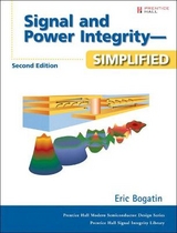
Signal Integrity - Simplified
Prentice Hall (Verlag)
978-0-13-066946-9 (ISBN)
- Titel erscheint in neuer Auflage
- Artikel merken
This book describes in the simplest possible terms, the signal integrity problems and the fundamental principles needed to understand how the physical design influences signal integrity. Most easily defined, signal integrity is all about how the physical design of the interconnects -- printed circuit board traces, connectors, IC packages and cables -- corrupt the perfect, pristine signals coming off the chips. The electrical properties of the interconnects play a key role in all electronic products operating above 50 MHz clock frequency, such as computers, wireless, rf and telecommunications products. Interconnects can degrade the electrical performance of a system in four ways: ringing, cross talk, noise in the power and ground distribution network and electromagnetic interference (EMI). These signal integrity problems can be reduced to acceptable levels by careful design of the circuit board layout, materials selection and component design and selection. Any product designer that touches the product can have an impact on signal integrity. The key differentiator between our book and all the others written on signal integrity, is the starting level for the material.Most books either present a lot of mathematical derivation or present formulas as facts, merely describing what they are.
Bogatin's book offers explanations that will feed the intuition of the engineers, without hiding behind the equations.
ERIC BOGATIN, Chief Technology Officer at GigaTest Labs, has over 23 years of experience in the microelectronics industry. Before joining GigaTest, he worked with AT&T Bell Labs, Raychem Corporation, Sun Microsystems, and other leading microelectronics manufacturers. He received his B.S. degree in physics at MIT and his M.S. and Ph.D. degrees from the University of Arizona, Tucson, in 1980. Over the years, he has taught over 3,000 engineers and authored over 100 technical articles and books on signal integrity and interconnect design.
Preface.
1. Signal Integrity Is in Your Future.
What Is Signal Integrity? Signal Quality on a Single Net. Cross Talk. Rail-Collapse Noise. Electromagnetic Interference (EMI). Two Important Signal Integrity Generalizations. Trends in Electronic Products. The Need for a New Design Methodology. A New Product Design Methodology. Simulations. Modeling and Models. Creating Circuit Models from Calculation. Three Types of Measurements. The Role of Measurements. The Bottom Line.
2. Time and Frequency Domains.
The Time Domain. Sine Waves in the Frequency Domain. Shorter Time to a Solution in the Frequency Domain. Sine Wave Features. The Fourier Transform. The Spectrum of a Repetitive Signal. The Spectrum of an Ideal Square Wave. From the Frequency Domain to the Time Domain. Effect of Bandwidth on Rise Time. Bandwidth and Rise Time. What Does “Significant” Mean? Bandwidth of Real Signals. Bandwidth and Clock Frequency. Bandwidth of a Measurement. Bandwidth of a Model. Bandwidth of an Interconnect. Bottom Line.
3. Impedance and Electrical Models.
Describing Signal-Integrity Solutions in Terms of Impedance. What Is Impedance? Real vs Ideal Circuit Elements. Impedance of an Ideal Resistor in the Time Domain. Impedance of an Ideal Capacitor in the Time Domain. Impedance of an Ideal Inductor in the Time Domain. Impedance in the Frequency Domain. Equivalent Electrical Circuit Models. Circuit Theory and SPICE. Introduction to Modeling. The Bottom Line.
4. The Physical Basis of Resistance.
Translating Physical Design into Electrical Performance. The Only Good Approximation for the Resistance of Interconnects. Bulk Resistivity. Resistance per Length. Sheet Resistance. The Bottom Line.
5. The Physical Basis of Capacitance.
Current Flow in Capacitors. The Capacitance of a Sphere. Parallel Plate Approximation. Dielectric Constant. Power and Ground Planes and Decoupling Capacitance. Capacitance per Length. 2D Field Solvers. Effective Dielectric Constant. The Bottom Line.
6. The Physical Basis of Inductance.
What Is Inductance? Inductance Principle #1: There Are Circular Magnetic-Field Line Loops around All Currents. Inductance Principle #2: Inductance Is the Number of Webers of Field Line Loops around a Conductor per Amp of Current through It. Self-Inductance and Mutual Inductance. Inductance Principle #3: When the Number of Field Line Loops around a Conductor Changes, There Will Be a Voltage Induced across the Ends of the Conductor. Partial Inductance. Effective, Total, or Net Inductance and Ground Bounce. Loop Self- and Mutual Inductance. The Power-Distribution System (PDS) and Loop Inductance. Loop Inductance per Square of Planes. Loop Inductance of Planes and Via Contacts. Loop Inductance of Planes with a Field of Clearance Holes. Loop Mutual Inductance. Equivalent Inductance. Summary of Inductance. Current Distributions and Skin Depth. High-Permeability Materials. Eddy Currents. The Bottom Line.
7. The Physical Basis of Transmission Lines.
Forget the Word Ground. The Signal. Uniform Transmission Lines. The Speed of Electrons in Copper. The Speed of a Signal in a Transmission Line. Spatial Extent of the Leading Edge. “Be the Signal”. The Instantaneous Impedance of a Transmission Line. haracteristic Impedance and Controlled Impedance. Famous Characteristic Impedances. The Impedance of a Transmission Line. Driving a Transmission Line. Return Paths. When Return Paths Switch Reference Planes. A First-Order Model of a Transmission Line. Calculating Characteristic Impedance with Approximations. Calculating the Characteristic Impedance with a 2D Field Solver. An n-Section Lumped Circuit Model. Frequency Variation of the Characteristic Impedance. The Bottom Line.
8. Transmission Lines and Reflections.
Reflections at Impedance Changes. Why Are There Reflections? Reflections from Resistive Loads. Source Impedance. Bounce Diagrams. Simulating Reflected Waveforms. Measuring Reflections with a TDR. Transmission Lines and Unintentional Discontinuities. When to Terminate. The Most Common Termination Strategy for Point-to-Point Topology. Reflections from Short Series Transmission Lines. Reflections from Short-Stub Transmission Lines. Reflections from Capacitive End Terminations. Reflections from Capacitive Loads in the Middle of a Trace. Capacitive Delay Adders. Effects of Corners and Vias. Loaded Lines. Reflections from Inductive Discontinuities. Compensation. The Bottom Line.
9. Lossy Lines, Rise-Time Degradation, and Material Properties.
Why Worry About Lossy Lines. Losses in Transmission Lines. Sources of Loss: Conductor Resistance and Skin Depth. Sources of Loss: The Dielectric. Dissipation Factor. The Real Meaning of Dissipation Factor. Modeling Lossy Transmission Lines. Characteristic Impedance of a Lossy Transmission Line. Signal Velocity in a Lossy Transmission Line. Attenuation and the dB. Attenuation in Lossy Lines. Measured Properties of a Lossy Line in the Frequency Domain. The Bandwidth of an Interconnect. Time-Domain Behavior of Lossy Lines. Improving the Eye Diagram of a Transmission Line. Pre-emphasis and Equalization. The Bottom Line.
10. Cross Talk in Transmission Lines.
Superposition. Origin of Coupling: Capacitance and Inductance. Cross Talk in Transmission Lines: NEXT and FEXT. Describing Cross Talk. The SPICE Capacitance Matrix. The Maxwell Capacitance Matrix and 2D Field Solvers. The Inductance Matrix. Cross Talk in Uniform Transmission Lines and Saturation Length. Capacitively Coupled Currents. Inductively Coupled Currents. Near-End Cross Talk. Far-End Cross Talk. Decreasing Far-End Cross Talk. Simulating Cross Talk. Guard Traces. Cross Talk and Dielectric Constant. Cross Talk and Timing. Switching Noise. Summary of Reducing Cross Talk. The Bottom Line.
11. Differential Pairs and Differential Impedance.
Differential Signaling. A Differential Pair. Differential Impedance with No Coupling. The Impact from Coupling. Calculating Differential Impedance. The Return-Current Distribution in a Differential Pair. Odd and Even Modes. Differential Impedance and Odd-Mode Impedance. Common Impedance and Even-Mode Impedance. Differential and Common Signals and Odd- and Even-Mode Voltage Components. Velocity of Each Mode and Far-End Cross Talk. Ideal Coupled Transmission-Line Model or an Ideal Differential Pair. Measuring Even- and Odd-Mode Impedance. Terminating Differential and Common Signals. Conversion of Differential to Common Signals. EMI and Common Signals. Cross Talk in Differential Pairs. Crossing a Gap in the Return Path. To Tightly Couple or Not to Tightly Couple. Calculating Odd and Even Modes from Capacitance- and Inductance-Matrix Elements. The Characteristic Impedance Matrix. The Bottom Line.
Appendix A.
Appendix B.
Appendix C.
Index.
About the Author.
| Erscheint lt. Verlag | 25.9.2003 |
|---|---|
| Verlagsort | Upper Saddle River |
| Sprache | englisch |
| Maße | 186 x 238 mm |
| Gewicht | 1086 g |
| Themenwelt | Technik ► Elektrotechnik / Energietechnik |
| ISBN-10 | 0-13-066946-6 / 0130669466 |
| ISBN-13 | 978-0-13-066946-9 / 9780130669469 |
| Zustand | Neuware |
| Informationen gemäß Produktsicherheitsverordnung (GPSR) | |
| Haben Sie eine Frage zum Produkt? |
aus dem Bereich
