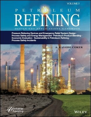
Petroleum Refining Design and Applications Handbook, Volume 5
Wiley-Scrivener (Verlag)
978-1-394-20698-8 (ISBN)
- Lieferbar (Termin unbekannt)
- Versandkostenfrei innerhalb Deutschlands
- Auch auf Rechnung
- Verfügbarkeit in der Filiale vor Ort prüfen
- Artikel merken
This fifth and final volume in the “Petroleum Refining Design and Applications Handbook” set, this book continues the most up-to-date and comprehensive coverage of the most significant and recent changes to petroleum refining, presenting the state-of-the-art to the engineer, scientist, or student.
Besides the list below, this groundbreaking new volume describes blending of products from the refinery, applying the ternary diagrams and classifications of crude oils, flash point blending, pour point blending, aniline point blending, smoke point and viscosity blending, cetane and diesel indices. The volume further reviews refinery operational cost, cost allocation of actual usage, project and economic evaluation involving cost estimation, cash flow involving return on investment, net present values, discounted cash flow rate of return, net present values, payback period, inflation and sensitivity analysis, and so on. It reviews global effects on the refining economy, carbon tax, carbon foot print, global warming potential, carbon dioxide equivalent, carbon credit, carbon offset, carbon price, and so on. It reviews sustainability in petroleum refining and alternative fuels (biofuels and so on), impact of the overall greenhouse effects, carbon capture and storage in refineries, process intensification in biodiesel, biofuel from green diesel, acid-gas removal and emerging technologies, carbon capture and storage, gas heated reformer unit, pressure swing adsorption process, steam methane reforming for fuel cells, grey, blue and green hydrogen production, new technologies for carbon capture and storage, carbon clean process design, refinery of the future, refining and petrochemical industry characteristics. The text is packed with Excel spreadsheet calculations and Honeywell UniSim Design software in some examples, and it includes an invaluable glossary of petroleum and petrochemical technical terminologies.
Useful as a textbook, this is also an excellent, handy go-to reference for the veteran engineer, a volume no chemical or process engineering library should be without. Written by one of the world’s foremost authorities, this book sets the standard for the industry and is an integral part of the petroleum refining renaissance. It is truly a must-have for any practicing engineer or student in this area.
A. Kayode Coker PhD, is Engineering Consultant for AKC Technology, an Honorary Research Fellow at the University of Wolverhampton, U.K., a former Engineering Coordinator at Saudi Aramco Shell Refinery Company (SASREF) and Chairman of the department of Chemical Engineering Technology at Jubail Industrial College, Saudi Arabia. He has been a chartered chemical engineer for more than 30 years. He is a Fellow of the Institution of Chemical Engineers, U.K. (C. Eng., FIChemE), and a senior member of the American Institute of Chemical Engineers (AIChE). He holds a B.Sc. honors degree in Chemical Engineering, a Master of Science degree in Process Analysis and Development and Ph.D. in Chemical Engineering, all from Aston University, Birmingham, U.K., and a Teacher’s Certificate in Education at the University of London, U.K. He has directed and conducted short courses extensively throughout the world and has been a lecturer at the university level. His articles have been published in several international journals. He is an author of 10 books in chemical engineering, a contributor to the Encyclopedia of Chemical Processing and Design, Vol 61 and a certified train - the mentor trainer. A Technical Report Assessor and Interviewer for chartered chemical engineers (IChemE) in the U.K. He is a member of the International Biographical Centre in Cambridge, U.K. (IBC) as Leading Engineers of the World for 2008. Also, he is a member of International Who’s Who of ProfessionalsTM and Madison Who’s Who in the U.S.
Preface xxiv
Acknowledgments xxvii
23 Pressure Relieving Devices and Emergency Relief System Design 1
23.0 Introduction 1
23.1 Types of Positive Pressure Relieving Devices (See Manufacturers’ Catalogs for Design Details) 2
23.2 Types of Valves/Relief Devices 6
Conventional Safety Relief Valve 6
Balanced Safety Relief Valve 7
Special Valves 7
Rupture Disk 7
Example 23.1 15
23.3 Materials of Construction 18
Safety and Relief Valves: Pressure-Vacuum Relief Values 18
Rupture Disks 19
23.4 General Code Requirements [1] 20
23.5 Relief Mechanisms 20
Reclosing Devices, Spring Loaded 20
Non-Reclosing Pressure Relieving Devices 21
23.6 Pressure Settings and Design Basis 21
23.7 Unfired Pressure Vessels Only, But Not Fired or Unfired Steam Boilers 24
Non-Fire Exposure 24
External Fire or Heat Exposure Only and Process Relief 24
23.8 Relieving Capacity of Combinations of Safety Relief Valves and Rupture Disks or Non-Reclosure Devices (Reference ASME Code, Par. UG-127, U-132) 24
Primary Relief 24
Rupture Disk Devices, [44] Par UG-127 25
Footnotes to ASME Code 26
23.9 Establishing Relieving or Set Pressures 27
Safety and Safety Relief Valves for Steam Service 28
23.10 Selection and Application 28
Causes of System Overpressure 28
23.11 Capacity Requirements Evaluation for Process Operation (Non-Fire) 29
Installation 34
23.12 Piping Design 37
Pressure Drops 37
Line Sizing 37
23.13 Selection Features: Safety, Safety-Relief Valves, and Rupture Disks 44
23.14 Calculations of Relieving Areas: Safety and Relief Valves 46
23.15 Standard Pressure Relief Valves Relief Area Discharge Openings 46
23.16 Sizing Safety Relief Type Devices for Required Flow Area at Time of Relief 47
23.17 Effects of Two-Phase Vapor-Liquid Mixture on Relief Valve Capacity 47
23.18 Sizing for Gases or Vapors or Liquids for Conventional Valves with Constant Backpressure Only 47
Procedure 48
Establish Critical Flow for Gases and Vapors 48
Example 23.2: Flow through Sharp Edged Vent Orifice (Adapted after [41]) 54
23.19 Orifice Area Calculations [42] 54
23.20 Sizing Valves for Liquid Relief: Pressure-Relief Valves Requiring Capacity Certification [5D] 60
23.21 Sizing Valves For Liquid Relief: Pressure Relief Valves Not Requiring Capacity Certification [5D] 61
23.22 Reaction Forces 66
Example 23.3 67
Solution 67
Example 23.4 69
Solution 70
23.23 Calculations of Orifice Flow Area using Pressure Relieving Balanced Bellows Valves, with Variable or Constant Backpressure 72
23.24 Sizing Valves for Liquid Expansion (Hydraulic Expansion of Liquid Filled Systems/ Equipment/Piping) 80
23.25 Sizing Valves for Subcritical Flow: Gas or Vapor But Not Steam [5d] 81
23.26 Emergency Pressure Relief: Fires and Explosions Rupture Disks 84
23.27 External Fires 84
23.28 Set Pressures for External Fires 85
23.29 Heat Absorbed 85
The Severe Case 85
23.30 Surface Area Exposed to Fire 86
23.31 Relief Capacity for Fire Exposure 87
23.32 Code Requirements for External Fire Conditions 87
23.33 Design Procedure 88
Example 23.5 88
Solution 88
23.34 Pressure Relief Valve Orifice Areas on Vessels Containing Only Gas, Unwetted Surface 92
23.35 Rupture Disk Sizing Design and Specification 93
23.36 Specifications to Manufacturer 93
23.37 Size Selection 94
23.38 Calculation of Relieving Areas: Rupture Disks for Non-Explosive Service 94
23.39 The Manufacturing Range (MR) 95
23.40 Selection of Burst Pressure for Disk, P b (Table 23.3) 95
Example 23.6: Rupture Disk Selection 98
23.41 Effects of Temperature on Disk 98
23.42 Rupture Disk Assembly Pressure Drop 101
23.43 Gases and Vapors: Rupture Disks [5a, Par, 4.8] 101
Volumetric Flow: scfm Standard Conditions (1.4.7 psia and 60°F) 102
Steam: Rupture Disk Sonic Flow; Critical Pressure = 0.55 and P 2 /p 1 is Less Than Critical Pressure Ratio of 0.55 103
23.44 API for Subsonic Flow: Gas or Vapor (Not Steam) 103
23.45 Liquids: Rupture Disk 104
23.46 Sizing for Combination of Rupture Disk and Pressure Relief Valve in Series Combination 105
Example 23.7: Safety Relief Valve for Process Overpressure 106
Example 23.8: Rupture Disk External Fire Condition 106
Solution 107
Heat Input 107
Total Heat Input (from Figure 23.30a) 107
Quantity of Vapor Released 107
Critical Flow Pressure 107
Disk Area 108
Example 23.9: Rupture Disk for Vapors or Gases; Non-Fire Condition 108
Solution 108
Example 23.10: Liquids Rupture Disk 109
Example 23.11: Liquid Overpressure, Figure 23.34 110
23.47 Pressure-Vacuum Relief for Low-Pressure Storage Tanks 110
23.48 Basic Venting For Low-Pressure Storage Vessels 111
23.49 Non-Refrigerated Above Ground Tanks; API-Std. 2000 112
23.50 Boiling Liquid Expanding Vapor Explosions (BLEVEs) 113
Ignition of Flammable Mixtures 116
23.51 Managing Runaway Reactions 116
Hydroprocessing Units 117
Acid/Base Reactions 118
Methanation 118
Alkylation Unit Acid Runaway 118
23.51.1 Runaway Reactions: DIERS 118
23.52 Hazard Evaluation in the Chemical Process Industries 120
23.53 Hazard Assessment Procedures 121
Exotherms 122
Accumulation 122
23.54 Thermal Runaway Chemical Reaction Hazards 122
Heat Consumed Heating the Vessel. The ɸ-Factor 123
Onset Temperature 124
Time-To-Maximum Rate 125
Maximum Reaction Temperature 125
Vent Sizing Package (VSP) 126
Vent Sizing Package 2 TM (VSP2 TM) 127
Advanced Reactive System Screening Tool (ARSST) 128
23.55 Two-Phase Flow Relief Sizing for Runaway Reaction 128
Runaway Reactions 131
Vapor Pressure Systems 132
Gassy Systems 132
Hybrid Systems 132
Simplified Nomograph Method 134
Vent Sizing Methods 138
Vapor Pressure Systems 138
Fauske’s Method 140
Gassy Systems 142
Homogeneous Two-Phase Venting Until Disengagement 143
Two-Phase Flow Through an Orifice 144
Conditions of Use 145
23.56 Discharge System 145
Design of The Vent Pipe 145
Safe Discharge 146
Direct Discharge to The Atmosphere 147
Example 23.12 147
Tempered Reaction 147
Solution 147
Example 23.13 149
Solution 149
Example 23.14 150
Solution 151
Example 23.15 152
Solution 152
DIERS Final Reports 155
23.57 Sizing for Two-Phase Fluids 155
Example 23.16 161
Solution 162
Example 23.17 164
Solution 164
Example 23.18 172
Example 23.19 177
Solution 178
Type 3 Integral Method [5] 179
Example 23.20 [76] 180
Solution 181
23.58 Flares/Flare Stacks 182
Flares 184
Sizing 184
Flame Length [5c] 186
Flame Distortion [5c] Caused by Wind Velocity 187
Flare Stack Height 189
Flaring Toxic Gases 194
Purging of Flare Stacks and Vessels/Piping 195
Pressure Purging 195
Example 23.21: Purge Vessel by Pressurization Following the Method of [41] 195
23.59 Compressible Flow for Discharge Piping 197
Design Equations for Compressible Fluid Flow for Discharge Piping 197
Critical Pressure, P crit 200
Compressibility Factor Z 201
Friction factor, f 202
Discharge Line Sizing 203
23.60 Vent Piping 204
Discharge Reactive Force 204
Example 23.22 205
Solution 206
Example 23.23: Flare and Relief Blowdon System 208
Solution 208
A Rapid Solution for Sizing Depressuring Lines [5c] 208
Codes and Standards 212
Discharge Locations 213
Process Safety Incidents with Relief Valve Failures and Flarestacks 214
A Case Study on Williams Geismar Olefins Plant, Geismar, Louisiana [95] 214
Process Flow of the Olefins 214
The Incident 216
Technical Analysis 219
Key Lessons 222
Explosions in Flarestacks 225
Relief Valves 227
Location 228
Relief Valve Registers 228
Relief Valve Faults [92] 229
Tailpipes [92] 230
GLOSSARY 230
Acronyms and Abbreviations 239
Nomenclature 240
Subscripts 244
Greek Symbols 244
References 245
World Wide Web on Two-Phase Relief Systems 247
24 Process Safety and Energy Management in Petroleum Refinery 249
24.1 Introduction 249
24.2 Process Safety 250
24.2.1 Process Safety Information 253
24.2.2 Conduct of Operations (COO) and Operational Discipline (OD) 254
Process Safety Culture: BP Refinery Explosion, Texas City, 2005 257
Detailed Description 257
Causes 258
Key Lessons 260
Process Safety Culture 260
Selected CSB Findings 260
Selected Baker Panel Finding 261
Process Knowledge Management 261
Training and Performance Assurance 261
Management of Change (MOC) 261
Asset Integrity and Reliability 261
24.2.3 Process Hazard Analysis 262
Safe Operating Limits 263
Impact on Other Process Safety Elements 264
24.3 General Process Safety Hazards in a Refinery 265
Desalters 266
Critical Operating Parameters Impacting Process Safety 266
The Quality of Aqueous Effluent from Desalters 267
Desalter Water Supply 267
Vibration within Relief Valve (RV) Pipework 267
Example of Process Safety Incidents and Hazards 267
Hydrotreating [2] 267
24.4 Example of Process Safety Incidents and Hazards 267
Catalytic Cracking [2] 270
24.5 Process Safety Hazards 270
Reforming 271
Alkylation [2] 271
Hydrotreating Units 271
24.5.1 Examples of Process Safety Incidents and Hazards 272
HF release, Texas City, TX, 1987 [2] 272
HF release, Corpus Christi, TX, 2009 272
HF release at Philadelphia Energy Solutions Refining and Marketing LLC (PES), Philadelphia 2019 273
Post-Incident Activities 276
Coking [2] 277
Equilon Anacortes Refinery Coking Plant Accident, 1998 277
Design Considerations 278
24.6 Hazards Relating to Equipment Failure 278
24.7 Columns and Other Process Pressure Vessels and Piping 279
Corrosion 279
Corrosion Inhibitors 280
24.8 Inadequate Design and Construction 290
Corrosion within “dead legs” 290
24.9 Inadequate Material of Construction Specification 290
24.10 Material Failures and Process Safety Prevention Programs 291
Piping Repair Incident at Tosco Avon Refinery, CA, USA 291
Lessons Learned from this accident 297
24.11 Hazard and Operability Studies (HAZOP) 297
Study Co-ordination 303
24.11.1 HAZOP Documentation Requirements 303
24.11.2 The Basic Concept of HAZOP 304
24.11.3 Division into Sections 304
Use of Guidewords 304
24.11.4 Conducting a HAZOP Study 305
Define Objective and Scope 306
Prepare for the Study 307
Record the Results 307
24.11.5 Hazop Case Study [8] 307
24.11.6 HAZOP of a Batch Process 308
Limitations of HAZOP Studies 315
Conclusions 315
24.12 Hazan 315
24.13 Fault Tree Analysis 317
24.14 Failure Mode and Effect Analysis (FMEA) 318
Methodology of FMEA 318
Definition of System to be Evaluated 318
Level of Analysis 318
Analysis of Failures 318
24.15 The Swiss Cheese Model 319
24.16 Bowtie Analysis 320
Validity Rules for Barriers 320
Example 322
Process Safety Isolation Practices in Petroleum Refinery and Chemical Process Industries 322
24.17 Inherently Safer Plant Design 325
Inherently Safer Plant Design in Reactor Systems 327
24.18 Energy Management in Petroleum Refinery 330
Total cost of energy 331
Energy Policy 331
Crude Distillation Unit 332
Heat Exchangers 332
Steam Traps 333
Optimization of Refinery Steam/Power System 333
Reducing fouling/surface cleaning/surface coating in heat exchanger/furnace 333
Pumping System 333
Electric Drives 334
Furnace System 334
Compressed Air 335
Flare System 335
24.18.1 Environmental Impact of Flaring 336
24.18.2 Environmental Impact of Petroleum Industry 337
24.18.3 Environmental Impact Assessment (EIA) 339
24.18.4 Pollution Control Strategies in Petroleum Refinery 340
24.18.5 Energy Management and Co2 Emissions in Refinery 345
24.19 Benchmarking in Refinery 345
Glossary 346
Acronyms and Abbreviations 354
References 354
25 Product Blending 357
25.0 Introduction 357
25.1 Blending Processes 360
25.1.1 Gasoline Blending 361
25.2 Ternary Diagram of Crude Oils 361
25.2.1 Elemental Analysis and Ternary Classification of Crude Oils 361
25.2.2 Reading a Ternary Diagram 363
Solution 364
Example 25.1 364
References 464
Bibliography 466
26 Cost Estimation and Economic Evaluation 467
26.1 Introduction 467
26.2 Refinery Operating Cost 468
26.2.1 Theoretical Sales Realization Valuation Method 470
Example 26.14 538
Solution 538
Product Quality 539
Standard Density 539
Blending Components 539
Constraining Properties 539
Quality Premiums/Discounts 539
A Case Study [44] 540
Problem Statement 540
Process Description 542
Catalytic Reformer 542
Naphtha Desulfurizer 544
Summary of Investment and Utilities Costs 545
Calculation of Direct Annual Operating Costs 545
On-Stream Time 546
Water Makeup 546
Power 546
Fuel 546
Royalties 547
Catalyst Consumption 548
Insurance 548
Local Taxes 548
Maintenance 548
Miscellaneous Supplies 548
Plant Staff and Operators 548
Calculations of Income before Income Tax 549
Summary of Direct Annual Operating Costs 549
Calculation of ROI 550
Carbon footprint 558
Global Warming Potential (GWP) 558
An Improved Method of Using GWPs 560
Solution 562
Carbon Dioxide Equivalent 565
Carbon Credit 566
Carbon Offset 566
Carbon Price 567
Nomenclature 567
References 568
Bibliography 569
27 Sustainability in Engineering, Petroleum Refining and Alternative Fuels 571
27.0 Introduction 571
27.1 Impacts on the Overall Greenhouse Effect 576
27.2 Carbon Capture and Storage in Refineries 578
27.3 Sustainability in the Refinery Industries 580
27.4 Sustainability in Engineering Design Principles 582
27.5 Alternative Fuels (Biofuels) 587
27.6 Process Intensification (PI) in Biodiesel 589
27.7 Biofuel from Green Diesel 592
Analysis 592
Processing of Biodiesel 592
27.7.1 Specifications of Biodiesel 596
Advantages 597
Disadvantages 597
27.7.2 Bioethanol 597
27.7.3 Biodiesel Production 601
Application 601
Process 602
Reaction Chemistry 603
Economics 603
27.7.4 An Alternative Process of Manufacturing Biodiesel 604
Reaction Chemistry 607
27.7.5 Biofuel from Algae 607
27.7.6 Economic Viability of Algae 608
27.8 Fast Pyrolysis 609
27.8.1 Fast Pyrolysis Principle 609
27.8.2 Fast Pyrolysis Technologies 610
27.8.3 Minerals of Biomass 611
27.8.4 Applications of Fast Pyrolysis Liquid 611
Heat and Power 611
27.8.5 Chemicals and Materials 613
27.8.6 Bio-Fuels-Fast Pyrolysis Bio-Oil (FPBO) from Biomass Residues 613
Feedstocks 614
27.8.7 Properties of Pyrolysis Oil 615
Main advantages 616
27.9 Acid Gas Removal 617
Chemical Solvent Processes 617
Physical Solvent Processes 617
27.9.1 Process Description of Amine Gas Treating 618
Chemical Reactions 618
For hydrogen sulfide H2 S removal: 618
For carbon dioxide (CO2) removal 618
Amines Used [48] 621
27.9.2 Equilibrium Data for Amine–Sour Gas Systems 625
27.9.3 Emerging Technologies [48] 625
Chemistry 627
27.9.4 Advanced Amine Based Solvents 627
Chemistry 628
Disadvantages of Amine Solvents 628
27.10 Alkaline Salt Process (Hot Carbonate) 629
Split Flow Process of Potassium Carbonate Process 630
Two Stage Process 630
27.11 Ionic Liquids 632
Disadvantages 632
Viscosity 633
Tunability 633
Design Suite R470 Technology) 634
Learning Objectives 634
Building the Simulation 636
Defining the Simulation Basis 636
Amines Property Package 636
Column Overview 636
Contactor 636
Adding the Basics 636
Adding the feed streams 636
Physical Unit Operations 638
Separator Operation 638
Contactor Operation 639
Valve Operation 641
Separator Operation 641
Heat Exchanger Operation 642
Regenerator Operation 643
Mixer Operation 644
Cooler Operation 646
Pump Operation 646
Adding Logical Unit Operations 647
Set Operation 647
Recycle Operation 648
Save your case 649
Analyzing the Results 649
Systems Thinking 657
Global Mechanisms 657
Best Available Techniques 657
Innovation 657
27.29 Conclusions 722
Glossary 723
References 729
Bibliography 732
Appendix D 733
Glossary of Petroleum and Petrochemical Technical Terminologies 809
About the Author 937
Index 939
| Erscheinungsdatum | 10.07.2023 |
|---|---|
| Sprache | englisch |
| Gewicht | 2318 g |
| Themenwelt | Naturwissenschaften ► Chemie ► Technische Chemie |
| Technik ► Elektrotechnik / Energietechnik | |
| ISBN-10 | 1-394-20698-4 / 1394206984 |
| ISBN-13 | 978-1-394-20698-8 / 9781394206988 |
| Zustand | Neuware |
| Informationen gemäß Produktsicherheitsverordnung (GPSR) | |
| Haben Sie eine Frage zum Produkt? |
aus dem Bereich


