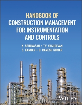
Handbook of Construction Management for Instrumentation and Controls
John Wiley & Sons Inc (Verlag)
978-1-394-19520-6 (ISBN)
In Handbook of Construction Management for Instrumentation and Controls, a team of experienced engineers delivers an expert discussion of what is required to install and commission complex, high-performance instrumentation and controls. The authors explain why, despite the ubiquitous availability of diverse international standards and instrument manufacturer data, the effective delivery of such projects involves significantly more than simply fitting instruments on panels.
The book covers material including site management, administration, operations, site safety, material management, workforce planning, instrument installation and cabling, instrument calibration, loop check and controller tuning, results recording, and participation in plant commissioning exercises. It also provides an extensive compendium of forms and checklists that can be used by professionals on a wide variety of installation and commissioning projects.
Handbook of Construction Management for Instrumentation and Controls also offers:
A thorough introduction to site operations, including the principles of equipment installation and testing
Comprehensive explorations of quality assurance and quality control procedures from installation to pre-commissioning to site hand-over
Practical discussions of site administration and operations, including planning and scheduling, site safety, and contractor permits-to-work, change and delay management
Detailed discussion of the installation and commissioning of complex instrumentation and control equipment
Perfect for specialty contractors and subcontractors, general contractors, consulting engineers, and construction managers, and as a reference book for institutes teaching courses on Industrial Instrumentation, Handbook of Construction Management for Instrumentation and Controls will also benefit students looking for a career in instrument installation.
K. Srinivasan (retired) was a senior engineer and head of process control systems at Foxboro (Australia), prior to which he was group head of design, construction, commissioning and maintenance for chemical, explosive and fertilizer plant instrumentation at ICI (India). He has a degree in physics and a post-graduate diploma in instrumentation from the Madras Institute of Technology. T.V. Vasudevan has a B.Sc. in physics and a post-graduate diploma in instrumentation technology, from the Madras Institute of Technology. His professional experience was mainly in the design & detailed engineering of oil and gas, refinery and petrochemical projects, power plants, cement plants, pharmaceutical plants and sugar plants. S. Kannan has a B.Sc. in physics and a post-graduate diploma in instrument technology from Madras Institute of Technology. He has 40 years of experience in the execution of field instrument installation, pre-commissioning works and project management of various instrumentation projects in refineries, petrochemicals, power and sugar plants. D. Ramesh Kumar has a B. Tech in instrumentation engineering from Madras Institute of Technology. He is a lead instrumentation & control system engineer with Oman Oil Refineries and Petroleum Industries Company in Oman.
About the Authors xvi
List of Figures xix
List of Tables xxiv
List of Forms xxv
Preface xxvii
Abbreviations xxix
1 Site Operations Manual – General 1
1.1 Introduction to the Handbook 1
1.2 Need for Handbook 2
1.3 Contract Types and Construction Management 2
1.4 Roadmap to Handbook 3
1.4.1 Oil and Gas Industry 3
1.4.2 Codes and Standards 3
1.4.3 Influence of Chemical Plant Nature on Construction 3
2 Construction Management – SITE Operations 7
2.1 SITE Management and Operations – Overview 7
2.2 Site Operations Manual 8
2.2.1 Site Construction Manager 8
2.2.2 Site Mobilisation 9
2.2.3 Site Organisation 9
2.2.3.1 Size 9
2.2.3.2 Organisation Structure and Manpower Resources 10
2.2.4 Engineering Administration 11
2.2.4.1 Engineering Standards On Site 12
2.2.4.2 Documents to be Available On Site 12
2.2.4.3 Material Management 12
2.2.4.4 Tools and Tackles On Site 12
2.2.4.5 Installation and Commissioning Schedule 12
2.2.4.6 Detailed Schedules for Installation and Shutdown 12
2.2.4.7 Clearance Certificates 12
2.2.4.8 Morning Meetings 13
2.2.4.9 QA Procedures 13
2.2.4.10 Safety Policy 14
2.2.4.11 Installation, Testing and Commissioning 14
2.2.5 Site Safety Practices and Rules 18
2.2.5.1 General Requirements 18
2.2.5.2 Administration 22
2.3 Site Administration and Cost Control 40
2.3.1 Plans and Schedules 40
2.3.2 Materials Management and Storage 40
2.3.2.1 Goods Receipt 40
2.3.2.2 Goods Issue 41
2.3.2.3 Spares 41
2.3.2.4 Software 42
2.3.2.5 Site Purchase 42
2.3.3 Staff Management 42
2.3.3.1 Site Organisation Structure 42
2.3.3.2 Site Working Hours 42
2.3.3.3 Charge Numbers For Site 43
2.3.3.4 Applying for Leave 43
2.3.3.5 Travel for Staff on Site 43
2.3.3.6 Discipline on Site 43
2.3.3.7 Performance Review for Staff On Site 43
2.3.3.8 Staff on Temporary Transfer to Site 43
2.3.4 Site Administration and Cost Control 43
2.3.4.1 Site Cost Monitoring 43
2.3.4.2 Site Cost Control 43
2.3.4.3 Revised Cost Estimates 44
2.3.4.4 Budget Updates 44
2.3.4.5 Corrective Action 44
2.3.4.6 Estimate at Completion (EAC) 44
2.3.4.7 Lessons Learned 44
2.3.5 Subcontractor Management 44
2.3.5.1 Subcontractor Check List 45
2.3.5.2 Obligations to the Subcontractor 45
2.3.5.3 Subcontractor Supervision 45
2.3.5.4 Quality in Work 45
2.3.5.5 Morning Meetings 45
2.3.5.6 Delays Caused by the Subcontractor 46
2.3.5.7 Breach of Contract by the Subcontractor 46
2.3.5.8 Subcontractor Safety 46
2.3.5.9 Claims by the Subcontractor 46
2.3.5.10 Progress Payment Claims 46
2.3.5.11 Delay Claims 46
2.3.5.12 Extension of Time Claims (EOT) 46
2.3.5.13 Dealing With the Client 47
2.3.6 Role of the Site Manager 47
2.3.7 Documents and Records On Site 47
2.3.7.1 Engineering Manuals 47
2.3.7.2 Engineering Drawings and Database 47
2.3.7.3 Registers / Files to be Maintained On Site 47
2.3.7.3.1 General 47
2.3.7.3.2 Contract Related 48
2.3.7.3.3 Subcontractor Related 48
2.3.8 Drawings / Documents / Manuals Issued to Subcontractor 48
2.3.8.1 System Related 48
2.3.8.2 Software on Site 48
2.3.8.3 Material Management Related 48
2.3.8.4 Safety Related 48
2.3.9 Overseas Construction Sites (Middle and Far East) 48
2.3.10 Communications and Reporting 49
2.3.10.1 Language Parlance 49
2.3.10.2 Types of Communication 49
2.3.10.3 Fortnightly Events Report 50
2.3.10.4 MPR and S-Curve 50
2.3.10.5 SIR and CWR 50
2.3.10.6 Safety Report 50
2.3.11 Project Completion and Closure 50
2.3.11.1 Check List for Project Closure 50
2.3.11.2 Formal Acceptance of Closure 50
2.3.12 PMC / Owner – Roles and Responsibilities 50
2.3.12.1 Data Sharing 50
2.3.12.2 Legal 51
2.4 Site Work Clearances and Permits 51
2.4.1 Introduction 51
2.4.2 Clearance Requirements 52
2.4.2.1 Clearance to Work Certificate 52
2.4.2.2 Types of Permits 52
2.4.2.3 Work Requiring a Clearance to Work 52
2.4.2.4 Requesting a Clearance to Work 52
2.4.2.5 Issuing a Clearance to Work 53
2.4.2.6 Changes to Scope of Work 53
2.4.2.7 Authorised Issuers 54
2.4.2.8 Documentation 54
2.5 Planning, Scheduling and Cost Control 54
2.5.1 General 54
2.5.2 Introduction to Planning 54
2.5.2.1 Wbs 54
2.5.2.2 CPD and CPM 57
2.5.2.3 Network Planning 58
2.5.3 Introduction to Scheduling (and Use of S-Curve) 61
2.5.4 Introduction to Reporting (Gantt Chart) 62
2.5.5 Introduction to Construction Cost Estimation 67
2.5.5.1 Overview 67
2.6 Technical Spec Tender and Template 72
2.6.1 Introduction 72
2.6.2 Scope of Works and Supply 73
2.6.2.1 Calibration Works 73
2.6.2.2 Supply and Installation Works 74
2.6.2.3 Cabling, Laying and Wiring Works 74
2.6.2.4 Piping and Tubing Hook-Up Works 74
2.6.2.5 Earthing Works 74
2.6.2.6 Loop Check Works 74
2.6.2.7 Documentation 75
2.6.2.8 Pre-Commissioning and Commissioning 75
2.6.2.9 Information From Tenderer 75
2.6.2.10 Mobilisation and SITE Management 75
2.6.2.11 Labour Laws and Law Requirements 76
2.6.2.12 Insurance 77
2.6.2.13 Contract Unassignable 77
2.6.2.14 Contractor’s Warranty 77
2.6.2.15 Contractor’s Guarantee 77
2.6.2.16 Inspection and Tests 78
2.6.2.17 Confidentiality 78
2.6.2.18 Contractor’s General Indemnity 78
2.6.2.19 Arbitration 78
2.6.2.20 Jurisdiction of Courts 78
2.6.2.21 Force Majeure 78
2.6.2.22 Annexure 1 to Section 2.6 78
2.6.2.23 Annexure 3 to Section 2.6 79
2.6.2.24 Annexure 4 Tender Schedule of Rates Format 79
3 Site Operations Manual – I&C 81
3.1 General 81
3.1.1 Engineering Handover 81
3.1.2 Site Structure for I&C Works Contract 85
3.1.3 Introduction to “Smart Instrumentation” Software 85
3.1.4 Preliminaries and Sequence of Works – I&C 87
3.2 Site Estimations and Preparations – I&C 90
3.2.1 Information Compilation 90
3.2.2 Man-Hour Estimate 92
3.2.3 Typical Engineering Cost Estimate Master Sheet 93
3.2.4 Documentation to be Available at Site 95
3.2.5 Tools, Tackles, Test Instruments / Equipment Miscellany 95
3.3 Field Installation 96
3.3.1 General 96
3.3.1.1 Overview 96
3.3.1.2 Equipment and Manpower Requirements 97
3.3.1.3 Instrument Mounting Locations 97
3.3.1.4 Accessibility 98
3.3.2 Field Installation – Instrument Accessories 100
3.3.2.1 Instrument Stanchion Installation 100
3.3.2.2 Instrument Sunshade Installation 103
3.3.2.3 Instrument Tag Plate Installation 106
3.3.2.4 Field Boxes and Panels Installation 106
3.3.3 Instrumentation Cabling Installation 109
3.3.3.1 Importance of Specification in Cable Laying 109
3.3.3.2 Cable Glands Installation 112
3.3.3.3 Cable Routing, Supporting and Fastening Installations 112
3.3.3.3.1 General 112
3.3.3.3.2 Cable Signal Segregation 112
3.3.3.3.3 Cable Routing Methods 114
3.3.3.3.4 Cabling From Field Junction Box to Control Room Marshalling Cabinets 115
3.3.3.3.5 Aboveground Cable Supporting System 115
3.3.3.3.6 Cable Tray-Ladder and Support Systems 115
3.3.3.3.7 Conduit and Conduit Fittings and Supports Installation 117
3.3.3.3.8 Cable Fastening 119
3.3.3.3.9 Underground Cable Supporting System 119
3.3.3.3.10 Computer False Floor 119
3.3.3.3.11 Cables in Trenches and/or Ducts 119
3.3.3.3.12 Duct Bank System Installation 122
3.3.3.3.13 Cable Entry Sealing 123
3.3.3.3.14 Cable Termination 123
3.3.3.3.15 Noise and Signal Interference Reduction 123
3.3.3.3.16 Cable Glands Installation 124
3.3.3.3.17 Connections at Field Instruments 124
3.3.3.3.18 Connections at Field Junction Boxes 124
3.3.3.3.19 Termination 125
3.3.3.3.20 Identification 126
3.3.3.3.21 Cable Supporting – Installation Detail 128
3.3.3.3.22 Cable Entry Sealing and Multi-Cable Transits (MCT) Installation 130
3.3.3.3.23 Cable End-to-End Installation 132
3.3.3.3.24 FF Cabling and Wiring – Special Note 133
3.3.3.3.25 Fibre Optic Network Cabling – Special Note 134
3.3.4 Field Instrumentation Earthing Installation 136
3.3.4.1 Grounding and Earthing Plan 136
3.3.4.2 Safety Ground Installation 139
3.3.4.3 Instrument DC and Shield Ground 140
3.3.4.4 Safety Ground Conductor Connections 140
3.3.4.5 Ground Fault Detection 140
3.3.5 Field Instrument-to-Process Installation 142
3.3.5.1 Instrument Impulse Tubing Installation 142
3.3.5.2 Pipe Manifolds and Direct Mounted Instruments – Installation 145
3.3.6 Online Instruments Installation 146
3.3.6.1 Pressure Gauges and Pressure Switches 146
3.3.6.2 Pressure and Differential Pressure Transmitters 147
3.3.7 In-Line Instruments Installation – Flow Meters 150
3.3.7.1 General Guidelines for Flow Meters 150
3.3.7.2 Orifice Plate and Flanges and Restriction Orifices 153
3.3.7.3 Venturi Tubes 154
3.3.7.4 Flow Nozzle 154
3.3.7.5 Wedge Flow Meter 154
3.3.7.6 Vortex Flow Meter 156
3.3.7.7 Ultrasonic Flow Meter Head 156
3.3.7.8 Coriolis Flow Meter 157
3.3.7.9 Electromagnetic (EM) Flow Meters 159
3.3.7.10 Variable Area Flow Meter (Rotameter) 161
3.3.7.11 Turbine Flow Meter 162
3.3.7.12 Positive Displacement or PD Flow Meter 164
3.3.7.13 Averaging Pitot Tube 165
3.3.8 In-Line instrumentation – Level Instruments on Vessels / Equipment 167
3.3.8.1 Types 167
3.3.8.2 General Guidelines For Installation 168
3.3.8.2.1 Standpipes / Stilling Well Fabrication Basics 168
3.3.8.2.2 Installation Guidelines 169
3.3.8.3 Level Gauges 169
3.3.8.3.1 Tubular / Reflex / Transparent Level Gauge / Indicators Installation 169
3.3.8.3.2 Magnetic Level Gauge / Indicators Installation 170
3.3.8.4 Guided Wave Radar (GWR) 170
3.3.8.5 Non-Contact Radar Level Transmitter Installation 172
3.3.8.6 Differential Pressure Level Instruments 174
3.3.8.7 Displacer Level Instruments 176
3.3.8.7.1 LVDT Type Displacer Level Instruments 176
3.3.8.7.2 Torque Tube Type Displacer Level Instruments 176
3.3.8.7.3 Installation Guidelines 176
3.3.8.8 Float Type Liquid Level Switches 177
3.3.8.8.1 Switch Mechanisms 177
3.3.8.8.2 Installation Guidelines 177
3.3.8.9 Magnetostrictive Level Transmitters 178
3.3.8.10 Capacitance Probe 179
3.3.8.11 Vibrating Fork Level Detector 180
3.3.8.12 Rotating Paddle Level Detector 182
3.3.8.13 Radiometric Level Detector 182
3.3.8.14 Tank Gauging – Manual 184
3.3.8.15 Automatic Tank Gauging (ATG) 184
3.3.8.15.1 Float Gauge–Servo 187
3.3.8.15.2 Hybrid Tank Gauging for Redundancy 187
3.3.9 Inline instruments – Temperature Instruments on Lines / Vessels / Equipment 187
3.3.9.1 General Guidelines for Temperature Measurements 187
3.3.9.2 Thermowells 188
3.3.9.3 Bi-Metal Thermometer 189
3.3.10 Process Analysers Installation 190
3.3.10.1 Introduction 190
3.3.10.2 Analyser Fundamentals 191
3.3.10.3 Analyser Installation Basics 201
3.3.10.3.1 Introduction to Installation 201
3.3.10.3.2 Analyser Enclosures Installation 203
3.3.10.3.3 General Sampling System Installation 205
3.3.10.4 Installation Guidelines 208
3.3.10.4.1 pH Analyser 208
3.3.10.4.2 Conductivity Analyser 209
3.3.10.4.3 Composition Analysis – Chromatographs 209
3.3.10.4.4 Oxygen Analyser 210
3.3.10.4.5 Sulphur Analyser 210
3.3.10.4.6 H2S Analyser 211
3.3.10.4.7 H2S – Oxygen Analyser 212
3.3.10.4.8 Oxygen Combustibles 212
3.3.10.4.9 Distillation Analyser 212
3.3.10.4.10 TOC Analyser 213
3.3.10.4.11 Oil-in-Water Analyser 213
3.3.10.4.12 Hydrogen-in-Gas Analyser 214
3.3.10.4.13 In-Line Hydrogen Sensor 214
3.3.10.4.14 Viscosity Analyser 214
3.3.10.4.15 Densitometer – Liquid 215
3.3.10.4.16 Densitometers – Gas and Wobbe Index 216
3.3.10.4.17 Moisture and Dew Point Analyser 216
3.3.10.4.18 Flash Point Analyser 216
3.3.10.4.19 Freeze Point and Cloud Point Analyser 217
3.3.10.4.20 RVP Analyser 218
3.3.10.4.21 Cold Filter Plug Point (CFPP) 218
3.3.10.4.22 Safety Gas Detectors 218
3.3.10.4.23 Analyser – Flare Emissions – EPA 220
3.3.10.4.24 Analyser – Others – EPA – Water 221
3.3.10.4.25 Analyser – CEM Other Than Flare Monitoring 221
3.3.10.4.26 Amadas 225
3.3.11 CV, MOV and PSV 226
3.3.11.1 Control Valves 226
3.3.11.2 Motor Operated Valves 229
3.3.11.3 Safety Valves 231
3.3.12 Instrument Air Piping and Pneumatic Transmission – Installation 233
3.3.13 Instrument Hydraulic Transmission Installation 235
3.3.14 Instrumentation Painting Requirements 237
3.4 Calibration 237
3.4.1 Introduction 237
3.4.1.1 Reference Accuracy vs. Bench Accuracy vs. Installed Accuracy 237
3.4.1.2 Accuracy in Terms of %FS (Full Scale) or % of Reading 238
3.4.2 Method or Procedure Statements 238
3.4.2.1 Method Statement 238
3.4.2.2 Guidelines 239
3.4.2.3 Calibration of HART and SMART Instruments 241
3.4.3 Calibration vs. Functional Test 242
3.4.4 Typical Hook-Ups and Calibration Steps 243
3.4.4.1 Typical Calibration Hook-Ups 243
3.4.4.2 Typical Instrument Calibration Steps 244
3.4.4.2.1 Pressure Instruments 244
3.4.4.2.2 Level Instruments 244
3.4.4.2.3 Temperature Instruments 246
3.4.4.2.4 Flow Instruments 246
3.4.4.2.5 Control Valves and Accessories 247
3.4.4.2.6 Safety – Relief Valves 250
3.4.4.2.7 Analysers – Calibration 250
3.5 Electrical Works For I&C 263
3.5.1 Scope of Works 263
3.5.2 Electrical and I&C Interface Activities 264
3.6 Control Room and Automation Works 273
3.6.1 Introduction to Control Room and Building 273
3.6.2 Introduction to System Architecture 274
3.6.3 Control Room (CR) Installation Works 276
3.6.3.1 Control Room I&C System – Installation Works 276
3.6.3.2 System Cabinet / Consoles / Workstations / Panel Installation 279
3.6.3.3 CR Conduit, Cable Tray / Ladder Installation 281
3.6.3.4 Power Cable, Signal Cable, Fibre Optic Cable Installation 281
3.6.3.5 Junction Box / FGS Panel Installation 282
3.6.3.6 FGS and Other Instruments Installation 282
3.6.4 Building Management and Access Control 282
3.6.4.1 Control Room HVAC 284
3.6.4.2 FGS for Control Room 287
3.6.4.3 Access Control 288
3.6.4.4 Rodent Control 289
3.6.4.5 Corrosion Monitoring – Control / SIH Rooms 289
3.6.4.6 Surge Protection Devices (SPD) 290
3.6.4.7 CCTV System 293
3.6.4.8 System Interfaces and Cyber Security – OT 294
3.6.4.8.1 System Interface Management 294
3.6.4.8.2 Cyber Security 295
3.6.4.8.3 Sys Interface – Contractor’s Role 295
3.6.4.8.4 MODBUS Inter System Links 297
3.7 Special Packs 298
3.7.1 Compressor I&C Packages 298
3.7.2 HVAC Systems – I&C 299
3.7.3 Satellite Instrument House (SIH) 300
3.7.4 Wireless I&C Preparations 302
3.7.5 Special Automation Packages 302
3.7.5.1 Tank Gauging Systems (TGS) 302
3.7.5.2 Tank Automation Systems (TAS) 303
3.7.5.3 Product Terminal Systems 304
3.7.5.4 Meter Prover Systems and Custody Transfers 307
3.7.5.5 Chemical and Catalyst Loading Systems 309
3.7.5.6 Variable Speed / Frequency Drive System 310
3.7.6 Emergency Isolation and Depressuring System 310
3.7.7 Special Third-Party Interfaces on Installations 312
3.7.7.1 IBR (India) 312
3.7.7.2 Nuclear Third-Party Inspections 313
3.7.7.3 Fire and Gas Third-Party Interfaces 314
3.8 QA/QC Plan – I&C 314
3.8.1 Introduction 314
3.8.2 Typical I&C QA/QC Plan 314
3.8.3 Information and Construction Check List 318
3.8.4 Loop Test 318
3.8.4.1 Loop Folder 318
3.8.4.2 Loop Test / Checks 320
3.8.4.2.1 Basics of Loop Checks 320
3.8.4.2.2 Loop Check Principles 322
3.8.4.2.3 Loop Check Methods for 4–20 mA or HART Transmitters 323
3.8.4.2.4 Detailed Loop Checks Procedure 324
3.8.5 Site Acceptance Test (SAT) Works 327
3.8.6 Site Integrated Test (SIT) Works 335
3.8.7 Pre-Commissioning Check Lists 335
3.8.7.1 Activity Log Register 335
3.8.7.2 Change Management 336
3.8.7.3 Pre-Commissioning Check List 336
3.9 Commissioning Works 338
3.9.1 Integrated Control System Commissioning 338
3.9.2 Plant Commissioning Preparation and Steps 338
3.9.3 Loop Tuning 340
3.9.3.1 Loop Tuning Basics 340
3.9.3.2 Loop Tuning – A Brief Introduction 341
3.9.3.2.1 Trial and Error Method 341
3.9.3.2.2 Open Loop Control Method 341
3.9.3.2.3 Closed Loop Control Method 342
3.9.4 Final Commissioned Plant Submissions 342
3.9.4.1 Final Activities 342
3.9.4.2 Dossier and Forms 343
3.10 Sign-Offs and Handover 346
3.10.1 Final Site Cleaning 346
3.10.2 Punch List – Final for Handover 346
3.10.2.1 Post Punch Check List for Commissioning 346
3.10.3 HAZOP and PSSR 347
3.10.4 Site Handover After I&C Works 348
4 Bulk Construction Material Specifications 349
4.1 Stanchions / Pipe Stands Specifications 349
4.2 Instrument Sunshade Specifications 351
4.3 Instrument Tag Plate Specifications 351
4.4 Junction Boxes Specifications 352
4.5 Cable Gland Specifications 355
4.6 Local Control Panel 355
4.7 Tubing and Tube Fitting Specifications 357
4.8 Valve Manifold Specifications 358
4.9 Instrument Cable Specifications 359
4.10 Network Cable Specifications 366
4.11 Instrument Concrete Duct Bank Specifications 367
4.12 Instrument Trays / Ladder Specifications 368
4.13 Conduit and Conduit Fitting Specifications 369
4.13.1 Conduits 369
4.13.2 Conduit Fittings 370
4.14 Multi-Cable Transit Specifications 370
4.15 Earthing / Grounding Material Specifications 371
5 Engineering Information 373
5.1 International Standards List 373
5.1.1 Standards Specific to I&C Construction Phase 373
5.1.2 Standards Specific to I&C Engineering Design 375
5.1.3 Associated Standards Useful to I&C 376
5.2 Useful Engineering Information 376
5.2.1 Thermocouple Tables 376
5.2.2 RTD Tables 377
5.2.3 Flange and Gasket Standards 377
5.2.3.1 Flanges 377
5.2.3.2 Gaskets 378
5.2.4 Corrosive Environment Class for Control Rooms 379
5.2.5 Hazardous Area Classification 380
5.2.6 Ingress Protection 381
5.2.7 Safety Integrity Limit (SIL) 381
5.2.8 Pressure Definitions 382
5.2.9 Typical Piping Connection Size for Instruments 382
5.2.10 Differential Pressure Level Measurement Suppression Elevation Calculation 383
5.2.11 Selected Engineering Conversions 384
5.2.12 Material Selection Table 387
5.2.13 Commonly Used Elastomers in Gaskets and Seals in Refineries 388
5.2.14 Control Valve Inherent Flow Characteristics 388
5.2.15 Physical Constants of Fluids 389
5.2.16 MODBUS – An Introduction 389
5.2.16.1 Introduction 389
5.2.16.2 How is the Data Stored in Standard MODBUS? 389
5.2.16.3 What is the Server ID? 390
5.2.16.4 What is a Function Code? 390
5.2.16.5 Error Checking 390
5.2.16.6 MODBUS Messages 390
5.2.16.7 Typical Wiring for MODBUS Communications 390
5.3 Typical Sample Drawings / Documents for Construction 392
5.4 Software in I&C Construction Management 400
5.4.1 Software Tools in Site Office Management 400
5.4.2 Field Bus Testing and Training Lab 400
5.4.3 Software Trends in Site Management 400
5.4.4 Loss and Profitability in Construction Contracts 400
6 Compendium of Forms 403
6.1 General 403
6.1.1 Site Office Personnel Forms Index 403
6.1.1.1 Employee Weekly Time Sheet Form 404
6.1.1.2 Employee Requisition Form 405
6.1.1.3 Travel Request Form 406
6.1.1.4 Position Specification Form 407
6.1.1.5 Employee Leave Request Form 408
6.1.1.6 Employee Expense Report Form – Sheets 1 and 2 409
6.1.2 Site Office Technical Forms Index 411
6.1.2.1 Customer Work Request Form – CWR 412
6.1.2.2 Internal Work Request Form – IWR 413
6.1.2.3 Information Request Form – IR 414
6.1.2.4 CHANGE Request Form – CR 415
6.1.2.5 Site Incident and Investigation Report Forms – SIR – Sheets 1 and 2 416
6.1.2.6 Goods Despatch Register Form – GDR 418
6.1.2.7 Goods Receipt Register Form – GRR 419
6.1.2.8 Stores Transaction Register Form – STR 420
6.1.2.9 SRR and SPIR Forms – Sheets 1 and 2 421
6.1.2.10 Work Permit and Clearance Forms (WCP) 425
6.2 Technical Forms – Typical 436
6.2.1 Trade Skill Test Forms 437
6.2.1.1 Instrument Fitter 437
6.2.1.2 Instrument Fabricator 438
6.2.1.3 Instrument Electrician 439
6.2.1.4 Instrument Technician (Calibration) 440
6.2.1.5 Instrument Supervisor 441
6.2.1.6 Instrument Foreman 442
6.2.2 Calibration Forms 443
6.2.2.1 Controllers and Receivers – Local 443
6.2.2.2 Control Valves – Actuators – Calibration and Inspection 444
6.2.2.3 Field Instrument – General 446
6.2.2.4 Field / Receiver Switch 447
6.2.2.5 Analyser Installation and Calibration Check 448
6.2.3 Field Installation Inspection Check Forms 450
6.2.3.1 Impulse Line Check 450
6.2.3.2 IA and Pneumatic – Piping System Check 452
6.2.3.3 IA and Pneumatic – Manifold System Check 454
6.2.3.4 Junction Box – Local Panel Check 456
6.2.3.5 Cable Drum Check 458
6.2.3.6 Cable Installation Check (Instrument and Fiber Optic Cables) 459
6.2.3.7 Cable Trunking Check 462
6.2.3.8 Field Cable Termination Check 464
6.2.3.9 Fieldbus Segment and Extension Check 465
6.2.3.10 Orifice Plate Check 468
6.2.3.11 Inline Flow Instrument Check 469
6.2.3.12 Online Flow Instrument Check 471
6.2.3.13 Level Instrument Check 472
6.2.3.14 Temperature Instrument Calibration and Check 474
6.2.3.15 MOV Installation Check 475
6.2.3.16 Safety Relief Valves Check 476
6.2.3.17 Package Instrument Installation Check 478
6.2.3.18 Analyser Shelter Installation Check 480
6.2.4 Control Room Works 480
6.2.4.1 Introduction 480
6.2.4.2 Control Room Requirements 481
6.2.4.3 Control Room Contracting Trends 481
6.2.4.4 Control Room Installation and Construction Phases 482
6.2.5 Loop Check Forms 484
6.2.5.1 Analogue Input Loop 484
6.2.5.2 Analogue Output – Control Valve Loop 485
6.2.5.3 Digital (Binary) Input Loop 487
6.2.5.4 Binary Output Loop 488
6.2.5.5 Motor and VSDS Loop 489
6.2.6 Pre-Commissioning Check Forms 490
6.2.6.1 Closed Loop Precomm Check Form 490
6.2.6.2 Open Loop Precomm Check Form 491
6.2.6.3 BPCS Precomm Check Form 492
6.2.6.4 Fire Detector Check Form 494
6.2.6.5 Gas Detector Check Form 495
6.2.7 Commissioning Check Forms 496
6.2.7.1 Instrument Commissioning Check Sheet – DCS 497
6.2.7.2 Alarm Action Commissioning Sheet 498
6.2.7.3 Interlock (Logic) Action Commissioning Check Sheet 499
6.2.7.4 Trip / Shutdown Action Commissioning Check Sheet 500
6.2.7.5 DCS Sequence Commissioning Test 501
6.2.7.6 Authorisation for Process Fluid Let In 502
Index 505
| Erscheinungsdatum | 16.12.2022 |
|---|---|
| Verlagsort | New York |
| Sprache | englisch |
| Maße | 226 x 282 mm |
| Gewicht | 1559 g |
| Themenwelt | Technik ► Bauwesen |
| Technik ► Elektrotechnik / Energietechnik | |
| ISBN-10 | 1-394-19520-6 / 1394195206 |
| ISBN-13 | 978-1-394-19520-6 / 9781394195206 |
| Zustand | Neuware |
| Haben Sie eine Frage zum Produkt? |
aus dem Bereich


