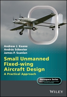
Small Unmanned Fixed-wing Aircraft Design
John Wiley & Sons Inc (Verlag)
978-1-119-40629-7 (ISBN)
Small Unmanned Fixed-wing Aircraft Design is the essential guide to designing, building and testing fixed wing UAVs (or drones). It deals with aircraft from two to 150 kg in weight and is based on the first-hand experiences of the world renowned UAV team at the UK’s University of Southampton.
The book covers both the practical aspects of designing, manufacturing and flight testing and outlines and the essential calculations needed to underpin successful designs. It describes the entire process of UAV design from requirements definition to configuration layout and sizing, through preliminary design and analysis using simple panel codes and spreadsheets to full CFD and FEA models and on to detailed design with parametric CAD tools. Its focus is on modest cost approaches that draw heavily on the latest digital design and manufacturing methods, including a strong emphasis on utilizing off-the-shelf components, low cost analysis, automated geometry modelling and 3D printing.
It deliberately avoids a deep theoretical coverage of aerodynamics or structural mechanics; rather it provides a design team with sufficient insights and guidance to get the essentials undertaken more pragmatically. The book contains many all-colour illustrations of the dozens of aircraft built by the authors and their students over the last ten years giving much detailed information on what works best. It is predominantly aimed at under-graduate and MSc level student design and build projects, but will be of interest to anyone engaged in the practical problems of getting quite complex unmanned aircraft flying. It should also appeal to the more sophisticated aero-modeller and those engaged on research based around fixed wing UAVs.
Andrew J. Keane is a Professor of Computational Engineering in the Faculty of Engineering and the Environment at the University of Southampton. He is the Director of the Rolls-Royce University Technology Center for Computational Engineering at the University and is a fellow of the RINA, IMechE and the Royal Academy of Engineering. András Sóbester is a Senior Lecturer of Aeronautical Engineering in the Faculty of Engineering and the Environment at the University of Southampton. His main research focus is on developing techniques for the aerodynamic optimization of aircraft. James P. Scanlan is a Professor of Design in the Faculty of Engineering and the Environment at the University of Southampton. He spent more than 10 years working in the aerospace industry and now manages a number of research programmes sponsored by BAE systems, Airbus, Rolls-Royce and the EPSRC. He is a Fellow of the Royal Aeronautical Society.
List of Figures xvii
List of Tables xxxiii
Foreword xxxv
Series Preface xxxvii
Preface xxxix
Acknowledgments xli
PART I INTRODUCING FIXED-WING UAVS
1 Preliminaries 3
1.1 Externally Sourced Components 4
1.2 Manufacturing Methods 5
1.3 Project DECODE 6
1.4 The Stages of Design 6
1.4.1 Concept Design 8
1.4.2 Preliminary Design 10
1.4.3 Detail Design 11
1.4.4 Manufacturing Design 12
1.4.5 In-service Design and Decommissioning 13
1.5 Summary 13
2 Unmanned Air Vehicles 15
2.1 A Brief Taxonomy of UAVs 15
2.2 The Morphology of a UAV 19
2.2.1 Lifting Surfaces 21
2.2.2 Control Surfaces 22
2.2.3 Fuselage and Internal Structure 23
2.2.4 Propulsion Systems 24
2.2.5 Fuel Tanks 24
2.2.6 Control Systems 24
2.2.7 Payloads 27
2.2.8 Take-off and Landing Gear 27
2.3 Main Design Drivers 29
PART II THE AIRCRAFT IN MORE DETAIL
3 Wings 33
3.1 Simple Wing Theory and Aerodynamic Shape 33
3.2 Spars 37
3.3 Covers 37
3.4 Ribs 38
3.5 Fuselage Attachments 38
3.6 Ailerons/Roll Control 40
3.7 Flaps 41
3.8 Wing Tips 42
3.9 Wing-housed Retractable Undercarriage 42
3.10 Integral Fuel Tanks 44
4 Fuselages and Tails (Empennage) 45
4.1 Main Fuselage/Nacelle Structure 45
4.2 Wing Attachment 47
4.3 Engine and Motor Mountings 48
4.4 Avionics Trays 50
4.5 Payloads – Camera Mountings 51
4.6 Integral Fuel Tanks 52
4.7 Assembly Mechanisms and Access Hatches 54
4.8 Undercarriage Attachment 55
4.9 Tails (Empennage) 57
5 Propulsion 59
5.1 Liquid-Fueled IC Engines 59
5.1.1 Glow-plug IC Engines 62
5.1.2 Spark Ignition Gasoline IC Engines 62
5.1.3 IC Engine Testing 65
5.2 Rare-earth Brushless Electric Motors 66
5.3 Propellers 68
5.4 Engine/Motor Control 70
5.5 Fuel Systems 70
5.6 Batteries and Generators 71
6 Airframe Avionics and Systems 73
6.1 Primary Control Transmitter and Receivers 73
6.2 Avionics Power Supplies 76
6.3 Servos 78
6.4 Wiring, Buses, and Boards 82
6.5 Autopilots 86
6.6 Payload Communications Systems 87
6.7 Ancillaries 88
6.8 Resilience and Redundancy 90
7 Undercarriages 93
7.1 Wheels 93
7.2 Suspension 95
7.3 Steering 95
7.4 Retractable Systems 97
PART III DESIGNING UAVS
8 The Process of Design 101
8.1 Goals and Constraints 101
8.2 Airworthiness 103
8.3 Likely Failure Modes 104
8.3.1 Aerodynamic and Stability Failure 105
8.3.2 Structural Failure 106
8.3.3 Engine/Motor Failure 107
8.3.4 Control System Failure 107
8.4 Systems Engineering 110
8.4.1 Work-breakdown Structure 110
8.4.2 Interface Definitions 112
8.4.3 Allocation of Responsibility 112
8.4.4 Requirements Flowdown 112
8.4.5 Compliance Testing 113
8.4.6 Cost and Weight Management 114
8.4.7 Design “Checklist” 117
9 Tool Selection 119
9.1 Geometry/CAD Codes 120
9.2 Concept Design 123
9.3 Operational Simulation and Mission Planning 125
9.4 Aerodynamic and Structural Analysis Codes 125
9.5 Design and Decision Viewing 125
9.6 Supporting Databases 126
10 Concept Design: Initial Constraint Analysis 127
10.1 The Design Brief 127
10.1.1 Drawing up a Good Design Brief 127
10.1.2 Environment and Mission 128
10.1.3 Constraints 129
10.2 Airframe Topology 130
10.2.1 Unmanned versus Manned – Rethinking Topology 130
10.2.2 Searching the Space of Topologies 133
10.2.3 Systematic “invention” of UAV Concepts 136
10.2.4 Managing the Concept Design Process 144
10.3 Airframe and Powerplant Scaling via Constraint Analysis 144
10.3.1 The Role of Constraint Analysis 144
10.3.2 The Impact of Customer Requirements 145
10.3.3 Concept Constraint Analysis – A Proposed Computational Implementation 145
10.3.4 The Constraint Space 146
10.4 A Parametric Constraint Analysis Report 146
10.4.1 About This Document 146
10.4.2 Design Brief 147
10.4.3 Unit Conversions 149
10.4.4 Basic Geometry and Initial Guesses 151
10.4.5 Preamble 151
10.4.6 Preliminary Calculations 152
10.4.7 Constraints 154
10.5 The Combined Constraint Diagram and Its Place in the Design Process 162
11 Spreadsheet-Based Concept Design and Examples 165
11.1 Concept Design Algorithm 166
11.2 Range 169
11.3 Structural Loading Calculations 169
11.4 Weight and CoG Estimation 170
11.5 Longitudinal Stability 170
11.6 Powering and Propeller Sizing 171
11.7 Resulting Design: Decode-1 174
11.8 A Bigger Single Engine Design: Decode-2 177
11.9 A Twin Tractor Design: SPOTTER 182
12 Preliminary Geometry Design 189
12.1 Preliminary Airframe Geometry and CAD 190
12.2 Designing Decode-1 with AirCONICS 192
13 Preliminary Aerodynamic and Stability Analysis 195
13.1 Panel Method Solvers – XFoil and XFLR5 196
13.2 RANS Solvers – Fluent 200
13.2.1 Meshing, Turbulence Model Choice, and y+ 204
13.3 Example Two-dimensional Airfoil Analysis 208
13.4 Example Three-dimensional Airfoil Analysis 210
13.5 3D Models of Simple Wings 212
13.6 Example Airframe Aerodynamics 214
13.6.1 Analyzing Decode-1 with XFLR5: Aerodynamics 215
13.6.2 Analyzing Decode-1 with XFLR5: Control Surfaces 221
13.6.3 Analyzing Decode-1 with XFLR5: Stability 223
13.6.4 Flight Simulators 227
13.6.5 Analyzing Decode-1 with Fluent 228
14 Preliminary Structural Analysis 237
14.1 Structural Modeling Using AirCONICS 240
14.2 Structural Analysis Using Simple Beam Theory 243
14.3 Finite Element Analysis (FEA) 245
14.3.1 FEA Model Preparation 246
14.3.2 FEA Complete Spar and Boom Model 250
14.3.3 FEA Analysis of 3D Printed and Fiber- or Mylar-clad Foam Parts 255
14.4 Structural Dynamics and Aeroelasticity 265
14.4.1 Estimating Wing Divergence, Control Reversal, and Flutter Onset
Speeds 266
14.5 Summary of Preliminary Structural Analysis 272
15 Weight and Center of Gravity Control 273
15.1 Weight Control 273
15.2 Longitudinal Center of Gravity Control 279
16 Experimental Testing and Validation 281
16.1 Wind Tunnels Tests 282
16.1.1 Mounting the Model 282
16.1.2 Calibrating the Test 284
16.1.3 Blockage Effects 284
16.1.4 Typical Results 287
16.2 Airframe Load Tests 290
16.2.1 Structural Test Instruments 290
16.2.2 Structural Mounting and Loading 293
16.2.3 Static Structural Testing 294
16.2.4 Dynamic Structural Testing 296
16.3 Avionics Testing 300
17 Detail Design: Constructing Explicit Design Geometry 303
17.1 The Generation of Geometry 303
17.2 Fuselage 306
17.3 An Example UAV Assembly 309
17.3.1 Hand Sketches 311
17.3.2 Master Sketches 311
17.4 3D Printed Parts 313
17.4.1 Decode-1: The Development of a Parametric Geometry for the SLS Nylon Wing Spar/Boom “Scaffold Clamp” 313
17.4.2 Approach 314
17.4.3 Inputs 314
17.4.4 Breakdown of Part 315
17.4.5 Parametric Capability 316
17.4.6 More Detailed Model 317
17.4.7 Manufacture 318
17.5 Wings 318
17.5.1 Wing Section Profile 320
17.5.2 Three-dimensional Wing 323
PART IV MANUFACTURE AND FLIGHT
18 Manufacture 331
18.1 Externally Sourced Components 331
18.2 Three-Dimensional Printing 332
18.2.1 Selective Laser Sintering (SLS) 332
18.2.2 Fused Deposition Modeling (FDM) 335
18.2.3 Sealing Components 335
18.3 Hot-wire Foam Cutting 337
18.3.1 Fiber and Mylar Foam Cladding 339
18.4 Laser Cutting 339
18.5 Wiring Looms 342
18.6 Assembly Mechanisms 342
18.6.1 Bayonets and Locking Pins 345
18.6.2 Clamps 346
18.6.3 Conventional Bolts and Screws 346
18.7 Storage and Transport Cases 347
19 Regulatory Approval and Documentation 349
19.1 Aviation Authority Requirements 349
19.2 System Description 351
19.2.1 Airframe 352
19.2.2 Performance 355
19.2.3 Avionics and Ground Control System 356
19.2.4 Acceptance Flight Data 358
19.3 Operations Manual 358
19.3.1 Organization, Team Roles, and Communications 359
19.3.2 Brief Technical Description 359
19.3.3 Operating Limits, Conditions, and Control 359
19.3.4 Operational Area and Flight Plans 360
19.3.5 Operational and Emergency Procedures 360
19.3.6 Maintenance Schedule 360
19.4 Safety Case 361
19.4.1 Risk Assessment Process 362
19.4.2 Failure Modes and Effects 362
19.4.3 Operational Hazards 363
19.4.4 Accident List 364
19.4.5 Mitigation List 364
19.4.6 Accident Sequences and Mitigation 366
19.5 Flight Planning Manual 368
20 Test Flights and Maintenance 369
20.1 Test Flight Planning 369
20.1.1 Exploration of Flight Envelope 369
20.1.2 Ranking of Flight Tests by Risk 370
20.1.3 Instrumentation and Recording of Flight Test Data 370
20.1.4 Pre-flight Inspection and Checklists 371
20.1.5 Atmospheric Conditions 371
20.1.6 Incident and Crash Contingency Planning, Post Crash Safety, Recording, and Management of Crash Site 371
20.2 Test Flight Examples 375
20.2.1 UAS Performance Flight Test (MANUAL Mode) 375
20.2.2 UAS CoG Flight Test (MANUAL Mode) 377
20.2.3 Fuel Consumption Tests 377
20.2.4 Engine Failure, Idle, and Throttle Change Tests 377
20.2.5 Autonomous Flight Control 378
20.2.6 Auto-Takeoff Test 380
20.2.7 Auto-Landing Test 380
20.2.8 Operational and Safety Flight Scenarios 381
20.3 Maintenance 381
20.3.1 Overall Airframe Maintenance 382
20.3.2 Time and Flight Expired Items 382
20.3.3 Batteries 383
20.3.4 Flight Control Software 383
20.3.5 Maintenance Record Keeping 384
21 Lessons Learned 385
21.1 Things that Have Gone Wrong and Why 388
PART V APPENDICES, BIBLIOGRAPHY, AND INDEX
A Generic Aircraft Design Flowchart 395
B Example AirCONICS Code for Decode-1 399
C Worked (Manned Aircraft) Detail Design Example 425
C.1 Stage 1: Concept Sketches 425
C.2 Stage 2: Part Definition 429
C.3 Stage 3: “Flying Surfaces” 434
C.4 Stage 4: Other Items 435
C.5 Stage 5: Detail Definition 435
Bibliography 439
Index 441
| Erscheinungsdatum | 28.09.2017 |
|---|---|
| Reihe/Serie | Aerospace Series |
| Mitarbeit |
Herausgeber (Serie): Peter Belobaba, Jonathan Cooper |
| Verlagsort | New York |
| Sprache | englisch |
| Maße | 170 x 246 mm |
| Gewicht | 1089 g |
| Themenwelt | Technik ► Fahrzeugbau / Schiffbau |
| Technik ► Luft- / Raumfahrttechnik | |
| Technik ► Maschinenbau | |
| ISBN-10 | 1-119-40629-3 / 1119406293 |
| ISBN-13 | 978-1-119-40629-7 / 9781119406297 |
| Zustand | Neuware |
| Informationen gemäß Produktsicherheitsverordnung (GPSR) | |
| Haben Sie eine Frage zum Produkt? |
aus dem Bereich


