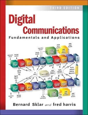
Digital Communications
Pearson (Verlag)
978-0-13-458856-8 (ISBN)
With remarkable clarity, Drs. Bernard Sklar and fred harris introduce every digital communication technology at the heart of today's wireless and Internet revolutions, with completely new chapters on synchronization, OFDM, and MIMO.
Building on the field's classic, best-selling introduction, the authors provide a unified structure and context for helping students and professional engineers understand each technology, without sacrificing mathematical precision. They illuminate the big picture and details of modulation, coding, and signal processing, tracing signals and processing steps from information source through sink. Throughout, readers will find numeric examples, step-by-step implementation guidance, and diagrams that place key concepts in clear context.
Understand signals, spectra, modulation, demodulation, detection, communication links, system link budgets, synchronization, fading, and other key concepts
Apply channel coding techniques, including advanced turbo coding and LDPC
Explore multiplexing, multiple access, and spread spectrum concepts and techniques
Learn about source coding: amplitude quantizing, differential PCM, and adaptive prediction
Discover the essentials and applications of synchronization, OFDM, and MIMO technology
More than ever, this is an ideal resource for practicing electrical engineers and students who want a practical, accessible introduction to modern digital communications.
This Third Edition includes online access to additional examples and material on the book's website.
Dr. Bernard Sklar has over 40 years of experience in technical design and management positions at Republic Aviation, Hughes Aircraft, Litton Industries, and The Aerospace Corporation, where he helped develop the MILSTAR satellite system. He is now head of advanced systems at Communications Engineering Services, a consulting company he founded in 1984. He has taught engineering courses at several universities, including UCLA and USC, and has trained professional engineers worldwide. Dr. Fredric J. Harris is a professor of electrical engineering and the CUBIC signal processing chair at San Diego State University and an internationally renowned expert on DSP and communication systems. He is also the co-inventor of the Blackman–Harris filter. He has extensively published many technical papers, the most famous being the seminal 1978 paper “On the Use of Windows for Harmonic Analysis with the Discrete Fourier Transform.” He is also the author of the textbook Multi-Rate Signal Processing for Communication Systems and the source coding chapter in the previous edition of this book.
Preface xxiii
Chapter 1 SIGNALS AND SPECTRA 1
1.1 Digital Communication Signal Processing 2
1.1.1 Why Digital? 2
1.1.2 Typical Block Diagram and Transformations 4
1.1.3 Basic Digital Communication Nomenclature 7
1.1.4 Digital Versus Analog Performance Criteria 9
1.2 Classification of Signals 10
1.2.1 Deterministic and Random Signals 10
1.2.2 Periodic and Nonperiodic Signals 10
1.2.3 Analog and Discrete Signals 10
1.2.4 Energy and Power Signals 11
1.2.5 The Unit Impulse Function 12
1.3 Spectral Density 13
1.3.1 Energy Spectral Density 13
1.3.2 Power Spectral Density 14
1.4 Autocorrelation 15
1.4.1 Autocorrelation of an Energy Signal 10
1.4.2 Autocorrelation of a Periodic (Power) Signal 16
1.5 Random Signals 17
1.5.1 Random Variables 17
1.5.2 Random Processes 19
1.5.3 Time Averaging and Ergodicity 21
1.5.4 Power Spectral Density and Autocorrelation of a Random Process 22
1.5.5 Noise in Communication Systems 27
1.6 Signal Transmission Through Linear Systems 30
1.6.1 Impulse Response 30
1.6.2 Frequency Transfer Function 31
1.6.3 Distortionless Transmission 32
1.6.4 Signals, Circuits, and Spectra 39
1.7 Bandwidth of Digital Data 41
1.7.1 Baseband Versus Bandpass 41`
1.7.2 The Bandwidth Dilemma 44
1.8 Conclusion 47
Chapter 2 FORMATTING AND BASEBAND MODULATION 53
2.1 Baseband Systems 54
2.2 Formatting Textual Data (Character Coding) 55
2.3 Messages, Characters, and Symbols 55
2.3.1 Example of Messages, Characters, and Symbols 56
2.4 Formatting Analog Information 57
2.4.1 The Sampling Theorem 57
2.4.2 Aliasing 64
2.4.3 Why Oversample? 67
2.4.4 Signal Interface for a Digital System 69
2.5 Sources of Corruption 70
2.5.1 Sampling and Quantizing Effects 71
2.5.2 Channel Effects 71
2.5.3 Signal-to-Noise Ratio for Quantized Pulses 72
2.6 Pulse Code Modulation 73
2.7 Uniform and Nonuniform Quantization 75
2.7.1 Statistics of Speech Amplitudes 75
2.7.2 Nonuniform Quantization 77
2.7.3 Companding Characteristics 77
2.8 Baseband Transmission 79
2.8.1 Waveform Representation of Binary Digits 79
2.8.2 PCM Waveform Types 80
2.8.3 Spectral Attributes of PCM Waveforms 83
2.8.4 Bits per PCM Word and Bits per Symbol 84
2.8.5 M-ary Pulse-Modulation Waveforms 86
2.9 Correlative Coding 88
2.9.1 Duobinary Signaling 88
2.9.2 Duobinary Decoding 89
2.9.3 Precoding 90
2.9.4 Duobinary Equivalent Transfer Function 91
2.9.5 Comparison of Binary and Duobinary Signaling 93
2.9.6 Polybinary Signaling 94
2.10 Conclusion 94
Chapter 3 BASEBAND DEMODULATION/DETECTION 99
3.1 Signals and Noise 100
3.1.1 Error-Performance Degradation in Communication Systems 100
3.1.2 Demodulation and Detection 101
3.1.3 A Vectorial View of Signals and Noise 105
3.1.4 The Basic SNR Parameter for Digital Communication Systems 112
3.1.5 Why Eb /N0 Is a Natural Figure of Merit 113
3.2 Detection of Binary Signals in Gaussian Noise 114
3.2.1 Maximum Likelihood Receiver Structure 114
3.2.2 The Matched Filter 117
3.2.3 Correlation Realization of the Matched Filter 119
3.2.4 Optimizing Error Performance 122
3.2.5 Error Probability Performance of Binary Signaling 126
3.3 Intersymbol Interference 130
3.3.1 Pulse Shaping to Reduce ISI 133
3.3.2 Two Types of Error-Performance Degradation 136
3.3.3 Demodulation/Detection of Shaped Pulses 140
3.4 Equalization 144
3.4.1 Channel Characterization 144
3.4.2 Eye Pattern 145
3.4.3 Equalizer Filter Types 146
3.4.4 Preset and Adaptive Equalization 152
3.4.5 Filter Update Rate 155
3.5 Conclusion 156
Chapter 4 BANDPASS MODULATION AND DEMODULATION/DETECTION 161
4.1 Why Modulate? 162
4.2 Digital Bandpass Modulation Techniques 162
4.2.1 Phasor Representation of a Sinusoid 163
4.2.2 Phase-Shift Keying 166
4.2.3 Frequency-Shift Keying 167
4.2.4 Amplitude Shift Keying 167
4.2.5 Amplitude-Phase Keying 168
4.2.6 Waveform Amplitude Coefficient 168
4.3 Detection of Signals in Gaussian Noise 169
4.3.1 Decision Regions 169
4.3.2 Correlation Receiver 170
4.4 Coherent Detection 175
4.4.1 Coherent Detection of PSK 175
4.4.2 Sampled Matched Filter 176
4.4.3 Coherent Detection of Multiple Phase-Shift Keying 181
4.4.4 Coherent Detection of FSK 184
4.5 Noncoherent Detection 187
4.5.1 Detection of Differential PSK 187
4.5.2 Binary Differential PSK Example 188
4.5.3 Noncoherent Detection of FSK 190
4.5.4 Required Tone Spacing for Noncoherent Orthogonal FSK Signaling 192
4.6 Complex Envelope 196
4.6.1 Quadrature Implementation of a Modulator 197
4.6.2 D8PSK Modulator Example 198
4.6.3 D8PSK Demodulator Example 200
4.7 Error Performance for Binary Systems 202
4.7.1 Probability of Bit Error for Coherently Detected BPSK 202
4.7.2 Probability of Bit Error for Coherently Detected, Differentially Encoded Binary PSK 204
4.7.3 Probability of Bit Error for Coherently Detected Binary Orthogonal FSK 204
4.7.4 Probability of Bit Error for Noncoherently Detected Binary Orthogonal FSK 206
4.7.5 Probability of Bit Error for Binary DPSK 208
4.7.6 Comparison of Bit-Error Performance for Various Modulation Types 210
4.8 M-ary Signaling and Performance 211
4.8.1 Ideal Probability of Bit-Error Performance 211
4.8.2 M-ary Signaling 212
4.8.3 Vectorial View of MPSK Signaling 214
4.8.4 BPSK and QPSK Have the Same Bit-Error Probability 216
4.8.5 Vectorial View of MFSK Signaling 217
4.9 Symbol Error Performance for M-ary Systems (M > 2) 221
4.9.1 Probability of Symbol Error for MPSK 221
4.9.2 Probability of Symbol Error for MFSK 222
4.9.3 Bit-Error Probability Versus Symbol Error Probability for Orthogonal Signals 223
4.9.4 Bit-Error Probability Versus Symbol Error Probability for Multiple-Phase Signaling 226
4.9.5 Effects of Intersymbol Interference 228
4.10 Conclusion 228
Chapter 5 COMMUNICATIONS LINK ANALYSIS 235
5.1 What the System Link Budget Tells the System Engineer 236
5.2 The Channel 236
5.2.1 The Concept of Free Space 237
5.2.2 Error-Performance Degradation 237
5.2.3 Sources of Signal Loss and Noise 238
5.3 Received Signal Power and Noise Power 243
5.3.1 The Range Equation 243
5.3.2 Received Signal Power as a Function of Frequency 247
5.3.3 Path Loss Is Frequency Dependent 248
5.3.4 Thermal Noise Power 250
5.4 Link Budget Analysis 252
5.4.1 Two Eb /N0 Values of Interest 254
5.4.2 Link Budgets Are Typically Calculated in Decibels 256
5.4.3 How Much Link Margin Is Enough? 257
5.4.4 Link Availability 258
5.5 Noise Figure, Noise Temperature, and System Temperature 263
5.5.1 Noise Figure 263
5.5.2 Noise Temperature 265
5.5.3 Line Loss 266
5.5.4 Composite Noise Figure and Composite Noise Temperature 269
5.5.5 System Effective Temperature 270
5.5.6 Sky Noise Temperature 275
5.6 Sample Link Analysis 279
5.6.1 Link Budget Details 279
5.6.2 Receiver Figure of Merit 282
5.6.3 Received Isotropic Power 282
5.7 Satellite Repeaters 283
5.7.1 Nonregenerative Repeaters 283
5.7.2 Nonlinear Repeater Amplifiers 288
5.8 System Trade-Offs 289
5.9 Conclusion 290
Chapter 6 CHANNEL CODING: PART 1: WAVEFORM CODES AND BLOCK CODES 297
6.1 Waveform Coding and Structured Sequences 298
6.1.1 Antipodal and Orthogonal Signals 298
6.1.2 M-ary Signaling 300
6.1.3 Waveform Coding 300
6.1.4 Waveform-Coding System Example 304
6.2 Types of Error Control 307
6.2.1 Terminal Connectivity 307
6.2.2 Automatic Repeat Request 307
6.3 Structured Sequences 309
6.3.1 Channel Models 309
6.3.2 Code Rate and Redundancy 311
6.3.3 Parity-Check Codes 312
6.3.4 Why Use Error-Correction Coding? 315
6.4 Linear Block Codes 320
6.4.1 Vector Spaces 320
6.4.2 Vector Subspaces 321
6.4.3 A (6, 3) Linear Block Code Example 322
6.4.4 Generator Matrix 323
6.4.5 Systematic Linear Block Codes 325
6.4.6 Parity-Check Matrix 326
6.4.7 Syndrome Testing 327
6.4.8 Error Correction 329
6.4.9 Decoder Implementation 332
6.5 Error-Detecting and Error-Correcting Capability 334
6.5.1 Weight and Distance of Binary Vectors 334
6.5.2 Minimum Distance of a Linear Code 335
6.5.3 Error Detection and Correction 335
6.5.4 Visualization of a 6-Tuple Space 339
6.5.5 Erasure Correction 341
6.6 Usefulness of the Standard Array 342
6.6.1 Estimating Code Capability 342
6.6.2 An (n, k) Example 343
6.6.3 Designing the (8, 2) Code 344
6.6.4 Error Detection Versus Error Correction Trade-Offs 345
6.6.5 The Standard Array Provides Insight 347
6.7 Cyclic Codes 349
6.7.1 Algebraic Structure of Cyclic Codes 349
6.7.2 Binary Cyclic Code Properties 351
6.7.3 Encoding in Systematic Form 352
6.7.4 Circuit for Dividing Polynomials 353
6.7.5 Systematic Encoding with an (n ? k)-Stage Shift Register 356
6.7.6 Error Detection with an (n ? k)-Stage Shift Register 358
6.8 Well-Known Block Codes 359
6.8.1 Hamming Codes 359
6.8.2 Extended Golay Code 361
6.8.3 BCH Codes 363
6.9 Conclusion 367
Chapter 7 CHANNEL CODING: PART 2: CONVOLUTIONAL CODES AND REED–SOLOMON CODES 375
7.1 Convolutional Encoding 376
7.2 Convolutional Encoder Representation 378
7.2.1 Connection Representation 378
7.2.2 State Representation and the State Diagram 382
7.2.3 The Tree Diagram 385
7.2.4 The Trellis Diagram 385
7.3 Formulation of the Convolutional Decoding Problem 388
7.3.1 Maximum Likelihood Decoding 388
7.3.2 Channel Models: Hard Versus Soft Decisions 390
7.3.3 The Viterbi Convolutional Decoding Algorithm 394
7.3.4 An Example of Viterbi Convolutional Decoding 394
7.3.5 Decoder Implementation 398
7.3.6 Path Memory and Synchronization 401
7.4 Properties of Convolutional Codes 402
7.4.1 Distance Properties of Convolutional Codes 402
7.4.2 Systematic and Nonsystematic Convolutional Codes 406
7.4.3 Catastrophic Error Propagation in Convolutional Codes 407
7.4.4 Performance Bounds for Convolutional Codes 408
7.4.5 Coding Gain 409
7.4.6 Best-Known Convolutional Codes 411
7.4.7 Convolutional Code Rate Trade-Off 413
7.4.8 Soft-Decision Viterbi Decoding 413
7.5 Other Convolutional Decoding Algorithms 415
7.5.1 Sequential Decoding 415
7.5.2 Comparisons and Limitations of Viterbi and Sequential Decoding 418
7.5.3 Feedback Decoding 419
7.6 Reed–Solomon Codes 421
7.6.1 Reed–Solomon Error Probability 423
7.6.2 Why R–S Codes Perform Well Against Burst Noise 426
7.6.3 R–S Performance as a Function of Size, Redundancy, and Code Rate 426
7.6.4 Finite Fields 429
7.6.5 Reed–Solomon Encoding 435
7.6.6 Reed–Solomon Decoding 439
7.7 Interleaving and Concatenated Codes 446
7.7.1 Block Interleaving 449
7.7.2 Convolutional Interleaving 452
7.7.3 Concatenated Codes 453
7.8 Coding and Interleaving Applied to the Compact Disc Digital Audio System 454
7.8.1 CIRC Encoding 456
7.8.2 CIRC Decoding 458
7.8.3 Interpolation and Muting 460
7.9 Conclusion 462
Chapter 8 CHANNEL CODING: PART 3: TURBO CODES AND LOW-DENSITY PARITY CHECK (LDPC) CODES 471
8.1 Turbo Codes 472
8.1.1 Turbo Code Concepts 472
8.1.2 Log-Likelihood Algebra 476
8.1.3 Product Code Example 477
8.1.4 Encoding with Recursive Systematic Codes 484
8.1.5 A Feedback Decoder 489
8.1.6 The MAP Algorithm 493
8.1.7 MAP Decoding Example 499
8.2 Low-Density Parity Check (LDPC) Codes 504
8.2.1 Background and Overview 504
8.2.2 The Parity-Check Matrix 505
8.2.3 Finding the Best-Performing Codes 507
8.2.4 Decoding: An Overview 509
8.2.5 Mathematical Foundations 514
8.2.6 Decoding in the Probability Domain 518
8.2.7 Decoding in the Logarithmic Domain 526
8.2.8 Reduced-Complexity Decoders 531
8.2.9 LDPC Performance 532
8.2.10 Conclusion 535
Appendix 8A: The Sum of Log-Likelihood Ratios 535
Appendix 8B: Using Bayes' Theorem to Simplify the Bit Conditional Probability 537
Appendix 8C: Probability that a Binary Sequence Contains an Even Number of Ones 537
Appendix 8D: Simplified Expression for the Hyperbolic Tangent of the Natural Log of a Ratio of Binary Probabilities 538
Appendix 8E: Proof that phi(x) = phi^-1(x) 538
Appendix 8F: Bit Probability Initialization 539
Chapter 9 MODULATION AND CODING TRADE-OFFS 549
9.1 Goals of the Communication System Designer 550
9.2 Error-Probability Plane 550
9.3 Nyquist Minimum Bandwidth 552
9.4 Shannon–Hartley Capacity Theorem 554
9.4.1 Shannon Limit 556
9.4.2 Entropy 557
9.4.3 Equivocation and Effective Transmission Rate 560
9.5 Bandwidth-Efficiency Plane 562
9.5.1 Bandwidth Efficiency of MPSK and MFSK Modulation 563
9.5.2 Analogies Between the Bandwidth-Efficiency and Error-Probability Planes 564
9.6 Modulation and Coding Trade-Offs 565
9.7 Defining, Designing, and Evaluating Digital Communication
Systems 566
9.7.1 M-ary Signaling 567
9.7.2 Bandwidth-Limited Systems 568
9.7.3 Power-Limited Systems 569
9.7.4 Requirements for MPSK and MFSK Signaling 570
9.7.5 Bandwidth-Limited Uncoded System Example 571
9.7.6 Power-Limited Uncoded System Example 573
9.7.7 Bandwidth-Limited and Power-Limited Coded System Example 575
9.8 Bandwidth-Efficient Modulation 583
9.8.1 QPSK and Offset QPSK Signaling 583
9.8.2 Minimum-Shift Keying 587
9.8.3 Quadrature Amplitude Modulation 591
9.9 Trellis-Coded Modulation 594
9.9.1 The Idea Behind Trellis-Coded Modulation 595
9.9.2 TCM Encoding 597
9.9.3 TCM Decoding 601
9.9.4 Other Trellis Codes 604
9.9.5 Trellis-Coded Modulation Example 606
9.9.6 Multidimensional Trellis-Coded Modulation 610
9.10 Conclusion 610
Chapter 10 SYNCHRONIZATION 619
10.1 Receiver Synchronization 620
10.1.1 Why We Must Synchronize 620
10.1.2 Alignment at the Waveform Level and Bit Stream Level 620
10.1.3 Carrier-Wave Modulation 620
10.1.4 Carrier Synchronization 621
10.1.5 Symbol Synchronization 624
10.1.6 Eye Diagrams and Constellations 625
10.2 Synchronous Demodulation 626
10.2.1 Minimizing Energy in the Difference Signal 628
10.2.2 Finding the Peak of the Correlation Function 629
10.2.3 The Basic Analog Phase-Locked Loop (PLL) 631
10.2.4 Phase-Locking Remote Oscillators 631
10.2.5 Estimating Phase Slope (Frequency) 633
10.3 Loop Filters, Control Circuits, and Acquisition 634
10.3.1 How Many Loop Filters Are There in a System? 634
10.3.2 The Key Loop Filters 634
10.3.3 Why We Want R Times R-dot 634
10.3.4 The Phase Error S-Curve 636
10.4 Phase-Locked Loop Timing Recovery 637
10.4.1 Recovering Carrier Timing from a Modulated Waveform 637
10.4.2 Classical Timing Recovery Architectures 638
10.4.3 Timing-Error Detection: Insight from the Correlation Function 641
10.4.4 Maximum-Likelihood Timing-Error Detection 642
10.4.5 Polyphase Matched Filter and Derivative Matched Filter 643
10.4.6 Approximate ML Timing Recovery PLL for a 32-Path PLL 647
10.5 Frequency Recovery Using a Frequency-Locked Loop (FLL) 652
10.5.1 Band-Edge Filters 654
10.5.2 Band-Edge Filter Non-Data-Aided Timing Synchronization 660
10.6 Effects of Phase and Frequency Offsets 664
10.6.1 Phase Offset and No Spinning: Effect on Constellation 665
10.6.2 Slow Spinning Effect on Constellation 667
10.6.3 Fast Spinning Effect on Constellation 670
10.7 Conclusion 672
Chapter 11 MULTIPLEXING AND MULTIPLE ACCESS 681
11.1 Allocation of the Communications Resource 682
11.1.1 Frequency-Division Multiplexing/Multiple Access 683
11.1.2 Time-Division Multiplexing/Multiple Access 688
11.1.3 Communications Resource Channelization 691
11.1.4 Performance Comparison of FDMA and TDMA 692
11.1.5 Code-Division Multiple Access 695
11.1.6 Space-Division and Polarization-Division Multiple Access 698
11.2 Multiple-Access Communications System and Architecture 700
11.2.1 Multiple-Access Information Flow 701
11.2.2 Demand-Assignment Multiple Access 702
11.3 Access Algorithms 702
11.3.1 ALOHA 702
11.3.2 Slotted ALOHA 705
11.3.3 Reservation ALOHA 706
11.3.4 Performance Comparison of S-ALOHA and R-ALOHA 708
11.3.5 Polling Techniques 710
11.4 Multiple-Access Techniques Employed with INTELSAT 712
11.4.1 Preassigned FDM/FM/FDMA or MCPC Operation 713
11.4.2 MCPC Modes of Accessing an INTELSAT Satellite 713
11.4.3 SPADE Operation 716
11.4.4 TDMA in INTELSAT 721
11.4.5 Satellite-Switched TDMA in INTELSAT 727
11.5 Multiple-Access Techniques for Local Area Networks 731
11.5.1 Carrier-Sense Multiple-Access Networks 731
11.5.2 Token-Ring Networks 733
11.5.3 Performance Comparison of CSMA/CD and Token-Ring Networks 734
11.6 Conclusion 736
Chapter 12 SPREAD-SPECTRUM TECHNIQUES 741
12.1 Spread-Spectrum Overview 742
12.1.1 The Beneficial Attributes of Spread-Spectrum Systems 742
12.1.2 A Catalog of Spreading Techniques 746
12.1.3 Model for Direct-Sequence Spread-Spectrum Interference Rejection 747
12.1.4 Historical Background 748
12.2 Pseudonoise Sequences 750
12.2.1 Randomness Properties 750
12.2.2 Shift Register Sequences 750
12.2.3 PN Autocorrelation Function 752
12.3 Direct-Sequence Spread-Spectrum Systems 753
12.3.1 Example of Direct Sequencing 755
12.3.2 Processing Gain and Performance 756
12.4 Frequency-Hopping Systems 759
12.4.1 Frequency-Hopping Example 761
12.4.2 Robustness 762
12.4.3 Frequency Hopping with Diversity 762
12.4.4 Fast Hopping Versus Slow Hopping 763
12.4.5 FFH/MFSK Demodulator 765
12.4.6 Processing Gain 766
12.5 Synchronization 766
12.5.1 Acquisition 767
12.5.2 Tracking 772
12.6 Jamming Considerations 775
12.6.1 The Jamming Game 775
12.6.2 Broadband Noise Jamming 780
12.6.3 Partial-Band Noise Jamming 781
12.6.4 Multiple-Tone Jamming 783
12.6.5 Pulse Jamming 785
12.6.6 Repeat-Back Jamming 787
12.6.7 BLADES System 788
12.7 Commercial Applications 789
12.7.1 Code-Division Multiple Access 789
12.7.2 Multipath Channels 792
12.7.3 The FCC Part 15 Rules for Spread-Spectrum Systems 793
12.7.4 Direct Sequence Versus Frequency Hopping 794
12.8 Cellular Systems 796
12.8.1 Direct-Sequence CDMA 796
12.8.2 Analog FM Versus TDMA Versus CDMA 799
12.8.3 Interference-Limited Versus Dimension-Limited Systems 801
12.8.4 IS-95 CDMA Digital Cellular System 803
12.9 Conclusion 814
Chapter 13 SOURCE CODING 823
13.1 Sources 824
13.1.1 Discrete Sources 824
13.1.2 Waveform Sources 829
13.2 Amplitude Quantizing 830
13.2.1 Quantizing Noise 833
13.2.2 Uniform Quantizing 836
13.2.3 Saturation 840
13.2.4 Dithering 842
13.2.5 Nonuniform Quantizing 845
13.3 Pulse Code Modulation 849
13.3.1 Differential Pulse Code Modulation 850
13.3.2 One-Tap Prediction 853
13.3.3 N-Tap Prediction 854
13.3.4 Delta Modulation 856
13.3.5 S-D Modulation 858
13.3.6 S-D A-to-D Converter (ADC) 862
13.3.7 S-D D-to-A Converter (DAC) 863
13.4 Adaptive Prediction 865
13.4.1 Forward Adaptation 865
13.4.2 Synthesis/Analysis Coding 866
13.5 Block Coding 868
13.5.1 Vector Quantizing 868
13.6 Transform Coding 870
13.6.1 Quantization for Transform Coding 872
13.6.2 Subband Coding 872
13.7 Source Coding for Digital Data 873
13.7.1 Properties of Codes 875
13.7.2 Huffman Code 877
13.7.3 Run-Length Codes 880
13.8 Examples of Source Coding 884
13.8.1 Audio Compression 884
13.8.2 Image Compression 889
13.9 Conclusion 898
Chapter 14 FADING CHANNELS 905
14.1 The Challenge of Communicating over Fading Channels 906
14.2 Characterizing Mobile-Radio Propagation 907
14.2.1 Large-Scale Fading 912
14.2.2 Small-Scale Fading 914
14.3 Signal Time Spreading 918
14.3.1 Signal Time Spreading Viewed in the Time-Delay Domain 918
14.3.2 Signal Time Spreading Viewed in the Frequency Domain 920
14.3.3 Examples of Flat Fading and Frequency-Selective Fading 924
14.4 Time Variance of the Channel Caused by Motion 926
14.4.1 Time Variance Viewed in the Time Domain 926
14.4.2 Time Variance Viewed in the Doppler-Shift Domain 929
14.4.3 Performance over a Slow- and Flat-Fading Rayleigh Channel 935
14.5 Mitigating the Degradation Effects of Fading 937
14.5.1 Mitigation to Combat Frequency-Selective Distortion 939
14.5.2 Mitigation to Combat Fast-Fading Distortion 942
14.5.3 Mitigation to Combat Loss in SNR 942
14.5.4 Diversity Techniques 944
14.5.5 Modulation Types for Fading Channels 946
14.5.6 The Role of an Interleaver 947
14.6 Summary of the Key Parameters Characterizing Fading Channels 951
14.6.1 Fast-Fading Distortion: Case 1 951
14.6.2 Frequency-Selective Fading Distortion: Case 2 952
14.6.3 Fast-Fading and Frequency-Selective Fading
Distortion: Case 3 953
14.7 Applications: Mitigating the Effects of Frequency-Selective Fading 955
14.7.1 The Viterbi Equalizer as Applied to GSM 955
14.7.2 The Rake Receiver Applied to Direct-Sequence Spread-Spectrum (DS/SS) Systems 958
14.8 Conclusion 960
Chapter 15 THE ABCs OF OFDM (ORTHOGONAL
FREQUENCY- DIVISION MULTIPLEXING) 971
15.1 What Is OFDM? 972
15.2 Why OFDM? 972
15.3 Getting Started with OFDM 973
15.4 Our Wish List (Preference for Flat Fading and Slow Fading) 974
15.4.1 OFDM's Most Important Contribution to Communications over Multipath Channels 975
15.5 Conventional Multi-Channel FDM versus Multi-Channel OFDM 976
15.6 The History of the Cyclic Prefix (CP) 977
15.6.1 Examining the Lengthened Symbol in OFDM 978
15.6.2 The Length of the CP 979
15.7 OFDM System Block Diagram 979
15.8 Zooming in on the IDFT 981
15.9 An Example of OFDM Waveform Synthesis 981
15.10 Summarizing OFDM Waveform Synthesis 983
15.11 Data Constellation Points Distributed over the Subcarrier Indexes 984
15.11.1 Signal Processing in the OFDM Receiver 986
15.11.2 OFDM Symbol-Time Duration 986
15.11.3 Why DC Is Not Used as a Subcarrier in Real Systems 987
15.12 Hermitian Symmetry 987
15.13 How Many Subcarriers Are Needed? 989
15.14 The Importance of the Cyclic Prefix (CP) in OFDM 989
15.14.1 Properties of Continuous and Discrete Fourier Transforms 990
15.14.2 Reconstructing the OFDM Subcarriers 991
15.14.3 A Property of the Discrete Fourier Transform (DFT) 992
15.14.4 Using Circular Convolution for Reconstructing an OFDM Subcarrier 993
15.14.5 The Trick That Makes Linear Convolution Appear
Circular 994
15.15 An Early OFDM Application: Wi-Fi Standard 802.11a 997
15.15.1 Why the Transform Size N Needs to Be Larger Than the Number of Subcarriers 999
15.16 Cyclic Prefix (CP) and Tone Spacing 1000
15.17 Long-Term Evolution (LTE) Use of OFDM 1001
15.17.1 LTE Resources: Grid, Block, and Element 1002
15.17.2 OFDM Frame in LTE 1003
15.18 Drawbacks of OFDM 1006
15.18.1 Sensitivity to Doppler 1006
15.18.2 Peak-to-Average Power Ratio (PAPR) and SC-OFDM 1006
15.18.3 Motivation for Reducing PAPR 1007
15.19 Single-Carrier OFDM (SC-OFDM) for Improved PAPR Over Standard OFDM 1007
15.19.1 SC-OFDM Signals Have Short Mainlobe Durations 1010
15.19.2 Is There an Easier Way to Implement SC-OFDM? 1011
15.20 Conclusion 1012
Chapter 16 THE MAGIC OF MIMO (MULTIPLE INPUT/MULTIPLE OUTPUT) 1017
16.1 What is MIMO? 1018
16.1.1 MIMO Historical Perspective 1019
16.1.2 Vectors and Phasors 1019
16.1.3 MIMO Channel Model 1020
16.2 Various Benefits of Multiple Antennas 1023
16.2.1 Array Gain 1023
16.2.2 Diversity Gain 1023
16.2.3 SIMO Receive Diversity Example 1026
16.2.4 MISO Transmit Diversity Example 1027
16.2.5 Two-Time Interval MISO Diversity Example 1028
16.2.6 Coding Gain 1029
16.2.7 Visualization of Array Gain, Diversity Gain, and Coding Gain 1029
16.3 Spatial Multiplexing 1031
16.3.1 Basic Idea of MIMO-Spatial Multiplexing (MIMO-SM) 1031
16.3.2 Analogy Between MIMO-SM and CDMA 1033
16.3.3 When Only the Receiver Has Channel-State Information (CSI) 1033
16.3.4 Impact of the Channel Model 1034
16.3.5 MIMO and OFDM Form a Natural Coupling 1036
16.4 Capacity Performance 1037
16.4.1 Deterministic Channel Modeling 1038
16.4.2 Random Channel Models 1040
16.5 Transmitter Channel-State Information (CSI) 1042
16.5.1 Optimum Power Distribution 1044
16.6 Space-Time Coding 1047
16.6.1 Block Codes in MIMO Systems 1047
16.6.2 Trellis Codes in MIMO Systems 1050
16.7 MIMO Trade-Offs 1051
16.7.1 Fundamental Trade-Off 1051
16.7.2 Trade-Off Yielding Greater Robustness for PAM and QAM 1052
16.7.3 Trade-Off Yielding Greater Capacity for PAM and QAM 1053
16.7.4 Tools for Trading Off Multiplexing Gain and Diversity Gain 1054
16.8 Multi-User MIMO (MU-MIMO) 1058
16.8.1 What Is MU-MIMO? 1059
16.8.2 SU-MIMO and MU-MIMO Notation 1059
16.8.3 A Real Shift in MIMO Thinking 1061
16.8.4 MU-MIMO Capacity 1067
16.8.5 Sum-Rate Capacity Comparison for Various Precoding Strategies 1081
16.8.6 MU-MIMO Versus SU-MIMO Performance 1082
16.9 Conclusion 1083
Index 1089
ONLINE ONLY:
Chapter 17 Encryption and Decryption
Appendix A A Review of Fourier Techniques
Appendix B Fundamentals of Statistical Decision Theory
Appendix C Response of a Correlator to White Noise
Appendix D Often-Used Identities
Appendix E S-Domain, Z-Domain, and Digital Filtering
Appendix F OFDM Symbol Formation with an N-Point Inverse Discrete Fourier Transform (IDFT)
Appendix G List of Symbols
| Erscheinungsdatum | 29.10.2018 |
|---|---|
| Sprache | englisch |
| Maße | 182 x 234 mm |
| Gewicht | 1940 g |
| Themenwelt | Technik ► Elektrotechnik / Energietechnik |
| Technik ► Nachrichtentechnik | |
| ISBN-10 | 0-13-458856-8 / 0134588568 |
| ISBN-13 | 978-0-13-458856-8 / 9780134588568 |
| Zustand | Neuware |
| Informationen gemäß Produktsicherheitsverordnung (GPSR) | |
| Haben Sie eine Frage zum Produkt? |
aus dem Bereich


