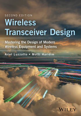
Wireless Transceiver Design
John Wiley & Sons Inc (Verlag)
978-1-118-93740-2 (ISBN)
The new edition has been adapted with instructors/lecturers, graduate/undergraduate students and RF engineers in mind. Non-RF engineers looking to acquire a basic understanding of the main related RF subjects will also find the book invaluable.
Ariel Luzzatto, L&L Scientific Ltd., Israel Motti Haridim, Holon Institute of Technology (HIT), Israel
Foreword xvi
To the Instructor xvii
About the Authors xviii
Acknowledgment xix
1 Introduction 1
1.1 Radio Frequency Systems 1
1.1.1 Conceptual RF system 1
1.1.2 The frequency spectrum 2
1.1.3 Cellular concept 3
1.2 Detailed Overview of Wireless Systems and Technologies 4
1.2.1 System types 4
1.2.2 Wireless network architectures 5
1.2.2.1 Wireless Personal Area Network 5
1.2.3 Wireless local area network 11
1.2.3.1 Wi-Fi 13
1.2.3.2 Wi-Fi Direct 14
1.2.4 Wireless wide area network 14
1.2.4.1 Cellular Systems 14
1.2.4.2 The Concept of Frequency Reuse 14
1.2.5 Access methods 20
1.2.5.1 Multiple access 20
1.2.5.2 Frequency division multiple access 20
1.2.5.3 Time division multiple access 21
1.2.5.4 Code division multiple access 21
1.2.5.5 Why to spread? 22
1.2.6 Transmit–receive regimes 24
1.2.6.1 Wireless transmission regimes (or modes) 24
1.2.6.2 Simplex mode 24
1.2.6.3 Half-duplex mode 25
1.2.6.4 Full duplex mode 25
1.2.6.5 Duplexing 25
1.2.6.6 Frequency division duplex 25
1.2.6.7 Time division duplex 26
Bibliography 26
2 Transceiver Architectures 27
2.1 Receiver Architectures 27
2.2 Superheterodyne Receiver 29
2.2.1 What is it and how it works 29
2.2.2 Pros and cons 33
2.2.3 Choosing the IF frequency 34
2.3 Direct Conversion Receiver 35
2.3.1 What is it and how it works 35
2.3.2 Pros and cons 35
2.4 Direct RF Sampling Receiver 36
2.4.1 What is it and how it works 36
2.4.1.1 Exercise: Determining sampling rate 40
2.4.2 Recovering I and Q channels in DRFS 40
2.4.2.1 Exercise: Recovering I and Q with bandwidth oversampling 41
2.5 Transmitter Architectures 42
2.6 Two Step Conversion Transmitter 43
2.6.1 What is it and how it works 43
2.6.2 Pros and cons 45
2.7 Direct Launch Transmitter 46
2.7.1 What is it and how it works 46
2.7.2 Pros and cons 46
2.8 Direct RF Sampling Transmitter 47
2.9 Transceiver Architectures 51
2.10 Full Duplex/Half-duplex Architecture 51
2.11 Simplex Architecture 52
2.12 Solved Exercises 53
2.13 Theory Behind Equations 59
2.13.1 DRFS transmitter 59
2.13.2 Sampling theorem reminder 60
Bibliography 62
3 Receiving Systems 63
3.1 Sensitivity 65
3.1.1 What is it and how it works 65
3.1.1.1 The definition of sensitivity 67
3.1.1.2 Exercise: Estimating a cell phone range 68
3.1.2 Interim sensitivity 69
3.1.2.1 Computing the noise factor of two cascaded stages 70
3.1.2.2 Exercise: Cascaded noise factor 71
3.1.2.3 Exercise: Computing SHR sensitivity 72
3.1.3 Measurement of sensitivity 74
3.1.3.1 Noise doubling approach 75
3.2 Co-channel Rejection 76
3.2.1 What is it and how it works 76
3.2.1.1 Definition of co-channel rejection 76
3.2.2 Measurement of co-channel rejection 77
3.3 Selectivity 78
3.3.1 What is it and how it works 78
3.3.1.1 Oscillator phase noise 78
3.3.1.2 Exercise: L (Δf) estimation 81
3.3.1.3 Selectivity mechanisms 82
3.3.1.4 The definition of selectivity 84
3.3.1.5 Exercise: DCR selectivity 85
3.3.2 Measurement of selectivity 85
3.4 Blocking 86
3.4.1 What is it and how it works 86
3.4.1.1 The definition of blocking 87
3.4.1.2 Exercise: Blocking-free distance 88
3.4.2 Measurement of blocking 89
3.5 Intermodulation Rejection 89
3.5.1 What is it and how it works 89
3.5.1.1 The definition of intermodulation 91
3.5.1.2 Effect of added gain (or loss) 92
3.5.1.3 Exercise: Intermodulation 94
3.5.2 Measurement of intermodulation 94
3.6 Image Rejection 95
3.6.1 What is it and how it works 95
3.6.1.1 The definition of image rejection 97
3.6.1.2 Exercise: IR and front filter 97
3.6.2 Measurement of image rejection 98
3.7 Half-IF Rejection 98
3.7.1 What is it and how it works 98
3.7.1.1 The definition of half-IF rejection 100
3.7.1.2 Exercise: HIFR and front filter 101
3.7.2 Measurement of half-IF rejection 102
3.8 Dynamic Range 102
3.8.1 What is it and how it works 102
3.8.1.1 The definition of dynamic range 103
3.8.2 Measurement of dynamic range 103
3.9 Duplex Desense 103
3.9.1 What is it and how it works 103
3.9.1.1 The definition of duplex desense 105
3.9.1.2 Exercise: Required T-R attenuation to keep DS ≤ 3dB 105
3.9.2 Measurement of duplex desense 106
3.10 Other Duplex Spurs 107
3.10.1 What they are and how they work 107
3.10.1.1 Duplex image rejection 107
3.10.1.2 Half duplex spur 107
3.10.1.3 Phantom duplex spur 108
3.11 Other Receiver Interferences 108
3.11.1 What they are and how they work 108
3.11.1.1 Self quieters 108
3.11.1.2 Able–baker spurs 110
3.11.1.3 Doppler blocking 110
3.11.1.4 Second-order distortion 110
3.11.1.5 Spurious free dynamic range 111
3.12 Solved Exercises 111
3.13 Theory Behind Equations 126
3.13.1 Sensitivity 126
3.13.2 Co-channel rejection 128
3.13.3 Selectivity 128
3.13.4 Intermodulation 129
3.13.5 Image rejection 130
3.13.6 Half-IF rejection 131
3.13.7 Duplexer mechanisms 132
3.13.7.1 Isolation mechanism 132
3.13.7.2 Noise attenuation mechanism 134
3.13.8 Duplex desense 135
3.14 Extension to Direct RF Sampling Receivers 136
3.14.1 ADC noise factor 136
3.14.1.1 Exercise: Computing ADC noise floor and noise figure 137
3.14.1.2 Exercise: Computing DRFS sensitivity 137
3.14.2 SNR, selectivity, and blocking in a DRFS receiver 138
3.14.2.1 Snr 139
3.14.2.2 Selectivity and blocking 140
3.14.2.3 Exercise: DRFS blocking 141
3.14.2.4 Imr 3 142
3.14.2.5 Exercise: Estimating IP3i of an ADC 142
3.14.3 Reminder on quantization noise 142
Bibliography 143
4 Transmitting Systems 145
4.1 Peak to Average Power Ratio 147
4.1.1 What is it and how it works 147
4.1.1.1 Exercise: PAPR of unfiltered 16 QAM 148
4.1.2 Measurement of PAPR 150
4.2 Nonlinearity in RF Power Amplifiers 150
4.2.1 What is it and how it works 150
4.2.2 Third-order dominated PA behavior 154
4.2.2.1 Exercise: Computation of third-order dominated PA coefficients 155
4.2.3 Fifth-order dominated PA behavior 157
4.2.3.1 Exercise: computation of fifth-order dominated PA coefficients 157
4.2.4 In-band spectral picture of PA output 159
4.2.5 Description of PA simulation methodology 160
4.2.5.1 The input signal v(t) 161
4.2.5.2 The output signal V[v(t)] 163
4.2.5.3 The input and output spectral picture 163
4.2.6 N-th order intermodulation distortion 163
4.2.6.1 Exercise: Coefficient-based versus SPICE simulation of spectral re-growth 168
4.2.6.2 Laboratory measurement of IMDN 171
4.2.7 N-th order input intercept point 171
4.2.7.1 Exercise: Estimating IMDN from IPNi 172
4.2.7.2 Exercise: Rule of thumb 173
4.2.7.3 Exercise: IPNi using voltages 173
4.3 Transmitter Specifications 174
4.3.1 Spectral mask 174
4.3.2 Error vector magnitude 174
4.3.2.1 Other causes of EVM degradation 176
4.3.3 Adjacent coupled power ratio 176
4.3.4 PA efficiency 177
4.3.5 Transmitter transients 178
4.3.5.1 Attack time 178
4.3.5.2 Frequency shift upon keying 179
4.3.6 Radiated emission 179
4.3.7 Conducted spurs 179
4.4 Enhancement Techniques 180
4.4.1 Linearization techniques 181
4.4.1.1 Cartesian feedback 181
4.4.1.2 Feed-forward 183
4.4.1.3 Pre-distortion 185
4.4.2 Envelope-tracking supply 186
4.5 Solved Exercises 186
4.6 Theory Behind Equations 198
4.6.1 Computation of PAPR for quasi-static RF signals 198
4.6.2 Analytic models for PA nonlinearity 201
4.6.3 Effects of PA nonlinearity on digital modulation 204
4.6.4 Effects of PA nonlinearity on spectral shape 205
4.6.5 Characterization of PA nonlinearity 210
4.6.5.1 N-th order intermodulation distortion 212
4.6.5.2 N-th order input intercept point 213
Bibliography 214
5 Synthesizers 216
5.1 Integer-N Synthesizer 216
5.1.1 What is it and how it works 216
5.1.1.1 The lock-up mechanism 219
5.1.1.2 Lock-up time 221
5.1.1.3 Exercise: Estimating integer-N lock time 224
5.1.1.4 Something more on reference spurs and pre-integration capacitor 225
5.1.1.5 Exercise: Estimating reference spurs attenuation 225
5.1.1.6 Something more on phase-frequency detector modes 226
5.2 Fractional-N Synthesizer 228
5.2.1 What is it and how it works 228
5.2.1.1 Exercise: Estimating fractional-N lock time 230
5.2.2 Example: Dual-count fractional-N 231
5.3 Direct Digital Synthesizer 232
5.3.1 What is it and how it works 232
5.3.1.1 Exercise: Basic DDS design 234
5.4 Integer-N/DDS Hybrid Synthesizer 235
5.4.1 What is it and how it works 235
5.5 Solved Exercises 236
5.6 Theory Behind Equations 244
5.6.1 Integer-N analysis 244
5.6.1.1 Transient analysis 246
5.6.1.2 Lock time analysis 250
Bibliography 251
6 Oscillators 253
6.1 Low-power Self-limiting Oscillators 254
6.1.1 What is it and how it works 254
6.1.1.1 The self-limiting oscillation mechanism 254
6.1.1.2 Oscillator phase noise 257
6.1.2 Practical circuits 258
6.1.2.1 Exercise: NAND gate-driven oscillator 260
6.1.2.2 Exercise: Bipolar transistor-driven oscillator 264
6.2 Oscillators Using Distributed Resonators 270
6.2.1 What is it and how it works 270
6.2.1.1 Crystal resonators 270
6.2.1.2 Transmission-line resonators 271
6.3 Solved Exercises 273
6.4 Theory Behind Equations 288
6.4.1 General π-topology filter analysis 288
6.4.2 Leeson’s equation 290
6.4.2.1 Narrowband FM 290
6.4.2.2 Narrowband-FM through narrow band-pass filters 291
6.4.2.3 Leeson’s model 293
6.4.2.4 Computing clock jitter from oscillator phase noise 296
6.4.3 Lumped equivalent of resonant transmission lines 299
6.4.3.1 Open-ended λ/4 resonator – lumped equivalent 300
6.4.3.2 Short-ended λ/4 resonator – lumped equivalent 301
6.4.4 Voltage controlled oscillators 301
Bibliography 302
7 Functional RF Blocks 303
7.1 Antenna 303
7.1.1 What is it? 303
7.1.2 How it works 303
7.1.3 Basic parameters of antennas 304
7.1.3.1 Radiation pattern 304
7.1.3.2 Directivity 304
7.1.3.3 Efficiency 305
7.1.3.4 Gain 305
7.1.3.5 Effective area 305
7.1.3.6 Input impedance and radiation resistance 305
7.1.3.7 Measurement of antenna input impedance 306
7.1.3.8 Beamwidth 307
7.1.3.9 Polarization 307
7.1.4 Antenna arrays 307
7.1.4.1 Pattern multiplication principle 308
7.1.5 Smart antennas 308
7.1.5.1 Phased array 308
7.1.6 Antenna types 308
7.1.6.1 Isotropic antennas 309
7.1.6.2 Dipole 309
7.1.6.3 Whip 309
7.1.6.4 Planar inverted-F 310
7.1.6.5 Slot 310
7.1.6.6 Microstrip (patch) antennas 311
7.1.7 Solved exercises 312
7.2 Low Noise Amplifier 313
7.2.1 What is it and how it works 313
7.2.2 Noise of two-port networks (classical approach) 314
7.2.2.1 MOS transistor thermal noise 316
7.2.2.2 Stability 317
7.2.2.3 Matching options 317
7.2.3 LNA topologies 318
7.2.3.1 Shunt resistor at input – resistor termination 318
7.2.3.2 Shunt-series feedback 319
7.2.3.3 Common gate LNA 319
7.2.3.4 CS with inductive source degeneration 320
7.3 Filters 323
7.3.1 Filter design 325
7.3.2 Filter families 326
7.3.2.1 Butterworth filter 326
7.3.2.2 Chebyshev filter 326
7.3.2.3 Elliptic filter 327
7.3.2.4 Bessel filter 327
7.3.3 Filter types 327
7.3.3.1 Preselector filter 327
7.3.3.2 Diplexer 328
7.3.3.3 IF filter 328
7.3.3.4 Harmonic filter 328
7.3.4 Filter technologies 328
7.3.4.1 Crystal filters 328
7.3.4.2 Surface acoustic wave filters 329
7.4 Power Amplifier 330
7.4.1 Amplifier classes 331
7.4.1.1 Class A 331
7.4.1.2 Class B 332
7.4.1.3 Class AB 333
7.4.1.4 class c 333
7.4.2 Design 334
7.5 Mixer 341
7.5.1 Performance measures 341
7.5.1.1 Conversion loss/gain 342
7.5.1.2 Noise figure 342
7.5.1.3 Linearity 342
7.5.1.4 Isolation 342
7.5.1.5 Spurs 342
7.5.2 Mixer types 342
7.5.2.1 Unbalanced mixers 343
7.5.2.2 Single-balanced mixers 343
7.5.2.3 Double-balanced mixers 343
7.5.3 MOSFET mixer 343
7.5.4 Bipolar mixer 345
Bibliography 346
8 Useful Reminders 347
8.1 The RF Channel 347
8.1.1 Large and small scale fading 347
8.1.1.1 Multipath fading 347
8.1.1.2 Propagation delay 348
8.1.1.3 Delay spread 348
8.1.1.4 Coherence bandwidth 349
8.1.2 Fade margin 349
8.1.3 Fading classification 349
8.1.3.1 Flat fading 350
8.1.3.2 Frequency-selective fading 350
8.1.3.3 Slow fading 350
8.1.3.4 Fast fading 350
8.1.3.5 Rayleigh fading 350
8.1.3.6 Rice fading 351
8.1.4 Doppler effect 351
8.2 Noise 352
8.2.1 Thermal noise 352
8.2.2 Signal to noise ratio 353
8.2.3 Noise factor and noise figure 353
8.2.3.1 Noise figure of cascaded stages 354
8.2.3.2 Noise floor 354
8.3 Propagation 355
8.3.1 Logarithmic scale 355
8.3.2 Friis formula 355
8.3.3 Two ray model 356
8.4 Path loss 357
8.5 Modulation 357
8.5.1 Amplitude modulation 357
8.5.2 Frequency modulation 359
8.5.2.1 FM transmitter 360
8.5.2.2 FM receiver 360
8.5.3 Modeling carrier phase noise as narrowband FM 361
8.6 Multiple Input Multiple Output 362
8.6.1 How many independent data streams are possible? 363
Bibliography 364
Appendix – Exemplary Exams 365
Index 369
| Erscheinungsdatum | 15.11.2016 |
|---|---|
| Verlagsort | New York |
| Sprache | englisch |
| Maße | 170 x 246 mm |
| Gewicht | 726 g |
| Themenwelt | Technik ► Elektrotechnik / Energietechnik |
| Technik ► Nachrichtentechnik | |
| ISBN-10 | 1-118-93740-6 / 1118937406 |
| ISBN-13 | 978-1-118-93740-2 / 9781118937402 |
| Zustand | Neuware |
| Informationen gemäß Produktsicherheitsverordnung (GPSR) | |
| Haben Sie eine Frage zum Produkt? |
aus dem Bereich


