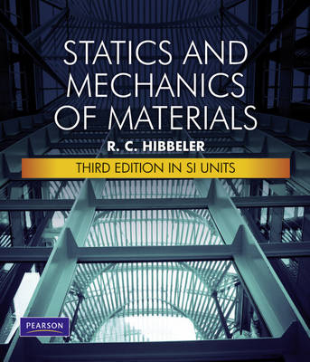
Statics Mechanics of Materials
Pearson Education Centre (Verlag)
978-981-06-8632-1 (ISBN)
- Titel erscheint in neuer Auflage
- Artikel merken
This four-coloured text in SI units is a combined abridged version of two of Hibbelers best-selling titles, namely Engineering Mechanics Statics 12th edition in SI Units and Mechanics of Materials 8th edition in SI Units. The books hallmark remains the same as the unabridged versions, that is having a strong emphasis on drawing a free-body diagram, as well as selecting an appropriate coordinate system and an associated sign convention when the equations of mechanics are applied. Many realistic analysis and design applications are presented, which involve mechanical elements and structural members often encountered in engineering practice.
New To This Edition
Content Revisions. Each section of the text has been carefully reviewed and in many areas, the material has been redeveloped to better explain concepts. Also, many new topics have been added. These include belt and screw friction, stress concentrations, torsion of noncircular shafts, using discontinuity functions to find beam deflections, and using the secant formula for eccentrically loaded columns. Artwork has been improved throughout the book to support these changes.
New Photos. Forty-four new and updated photos placed throughout the book are used to explain how relevant engineering principles apply in real-world situations, how to make an idealised model for analysis, and how materials behave under load.
Fundamental Problems. These problem sets can be considered as extended examples since they all have partial solutions and answers given at the back of the book. They are located just after each group of example problems. Fundamental Problems offer simple application of concepts taught, allowing students to develop their fundamental problem-solving skills before attempting to solve standard problems. In addition, they are useful for exam preparations, being an excellent review of engineering fundamentals.
Conceptual Problems. These analysis and design problem types involve conceptual situations that allow students to think through and apply mechanical principles in real-life conceptual situations as depicted in photos. They provide a means to develop the skill of reducing any such problem from its physical description to a symbolic representation to which the principles may be applied. Such conceptual problems can be assigned when students have developed a certain level of expertise on the subject matter. They work well in both individual and team projects.
New and More Homework Problems. Of the nearly 1,400 homework problems in the book, approximately 1,000 are new to this edition. They involve applications in many different fields of engineering. There are approximately 460 more problems found in this edition compared to the previous one, giving instructors a wider choice of problems to use for developing and testing their students problem-solving skills. Students also have more questions for practice.
New Example Problems. New example problems have been added while others have been modified to provide greater emphasis on the applications of important concepts.
Problems with Hints. Every problem marked with a bullet point () comes with hints such as a suggestion, key equation, or additional numerical result that is given along with the answer at the back of the book. These hints encourage students to attempt such problems on their own by providing additional checks to the solution.
Interactive Animations. Key principles that are difficult to visualise and understand now come with interactive animations. These animations help students visualise the forces at work in an engineering situation and see the relation between mathematical explanation and real structure. They break down complicated sequences into step-by-step movement of engineering parts and show how free-body diagrams can be derived. Being interactive, students can pause the animated sequence at multiple points to study and understand the underlying equations. It is an effective tool for instructors as it graphically explains difficult-to-understand concepts.
Video Solutions: Developed by Professor Edward Berger from the University of Virginia, our video solutions offer step-by-step solution walkthroughs of representative homework problems in each chapter. They come with detailed voice-over explanations and allow self-paced instruction with 24/7 accessibility. Students learn how to break down a complex problem into multiple steps in order to find a solution, reducing their reliance on instructors. These video solutions have been conveniently classified into SI and non-SI clusters.
Statics
1 General Principles
Chapter Objectives
1.1 Mechanics
1.2 Fundamental Concepts
1.3 Units of Measurement
1.4 The International System of Units
1.5 Numerical Calculations
1.6 General Procedure for Analysis
2 Force Vectors
Chapter Objectives
2.1 Scalars and Vectors
2.2 Vector Operations
2.3 Vector Addition of Forces
2.4 Addition of a System of Coplanar Forces
2.5 Cartesian Vectors
2.6 Addition of Cartesian Vectors
2.7 Position Vectors
2.8 Force Vector Directed Along a Line
2.9 Dot Product
3 Force System Resultants
Chapter Objectives
3.1 Moment of a ForceScalar Formulation
3.2 Cross Product
3.3 Moment of a ForceVector Formulation
3.4 Principle of Moments
3.5 Moment of a Force about a Specified Axis
3.6 Moment of a Couple
3.7 Simplification of a Force and Couple System
3.8 Further Simplification of a Force and Couple System
4 Equilibrium of a Rigid Body
Chapter Objectives
4.1 Conditions for Rigid-Body Equilibrium
4.2 Free-Body Diagrams
4.3 Equations of Equilibrium
4.4 Two- and Three-Force Members
4.5 Free-Body Diagrams
4.6 Equations of Equilibrium
4.7 Characteristics of Dry Friction
4.8 Problems Involving Dry Friction
4.9 Frictional Forces on Flat Belts
4.10 Frictional Forces on Screws
5 Structural Analysis
Chapter Objectives
5.1 Simple Trusses
5.2 The Method of Joints
5.3 Zero-Force Members
5.4 The Method of Sections
5.5 Frames and Machines
6 Center of Gravity, Centroid and Moment of Inertia
Chapter Objectives
6.1 Center of Gravity , Center of Mass, and the Centroid of a Body
6.2 Composite Bodies
6.3 Resultant of a Distributed Loading
6.4 Moments of Inertia for Areas
6.5 Parallel-Axis Theorem for an Area
6.6 Moments of Inertia for Composite Areas
Mechanics of Materials
7 Stress and Strain
Chapter Objectives
7.1 Introduction
7.2 Internal Resultant Loadings
7.3 Stress
7.4 Average Normal Stress in an Axially Loaded Bar
7.5 Average Shear Stress
7.6 Allowable Stress
7.7 Design of Simple Connections
7.8 Deformation
7.9 Strain
8 Mechanical Properties of Materials
Chapter Objectives
8.1 The Tension and Compression Test
8.2 The Stress-Strain Diagram
8.3 Stress-Strain Behavior of Ductile and Brittle Materials
8.4 Hookes Law
8.5 Strain Energy
8.6 Poissons Ratio
8.7 The Shear Stress-Strain Diagram
9 Axial Load
Chapter Objectives
9.1 Saint-Venants Principle
9.2 Elastic Deformation of an Axially Loaded Member
9.3 Principle of Superposition
9.4 Statically Indeterminate Axially Loaded Member
9.5 The Force Method of Analysis for Axially Loaded Members
9.6 Thermal Stress
9.7 Stress Concentrations
10 Torsion
Chapter Objectives
10.1 Torsional Deformation of a Circular Shaft
10.2 The Torsion Formula
10.3 Power Transmission
10.4 Angle of Twist
10.5 Statically Indeterminate Torque-Loaded Members
10.6 Solid Noncircular Shafts
10.7 Stress Concentration
11 Bending
Chapter Objectives
11.1 Shear and Moment Diagrams
11.2 Graphical Method for Constructing Shear and Moment Diagrams
11.3 Bending Deformation of a Straight Member
11.4 The Flexure Formula
11.5 Unsymmetric Bending
11.6 Stress Concentrations
12 Transverse Shear
Chapter Objectives
12.1 Shear in Straight Members
12.2 The Shear Formula
12.3 Shear Flow in Built-Up Members
13 Combined Loadings
Chapter Objectives
13.1 Thin-Walled Pressure Vessels
13.2 State of Stress Caused by Combined Loadings
14 Stress and Strain Transformation
Chapter Objectives
14.1 Plane-Stress Transformation
14.2 General Equations of Plane-Stress Transformation
14.3 Principal Stresses and Maximum In-Plane Shear Stress
14.4 Mohrs CirclePlane Stress
14.5 Absolute Maximum Shear Stress
14.6 Plane Strain
14.7 General Equations of Plane-Strain Transformation
14.8 Mohrs CirclePlane Strain
14.9 Strain Rosettes
14.10 Material-Property Relationships
15 Design of Beams and Shafts
Chapter Objectives
15.1 Basis for Beam Design
15.2 Prismatic Beam Design
15.3 Fully Stressed Beams
16 Deflection of Beams and Shafts
Chapter Objectives
16.1 The Elastic Curve
16.2 Slope and Displacement by Integration
16.3 Discontinuity Functions
16.4 Method of Superposition
16.5 Statically Indeterminate Beams and Shafts-Method of Superposition
17 Buckling of Columns
Chapter Objectives
17.1 Critical Load
17.2 Ideal Column with Pin Supports
17.3 Columns Having Various Types of Supports
17.4 The Secant Formula
17.5 Inelastic Buckling
Appendices
A. Mathematical Review and Expressions
B. Geometric Properties of An Area and Volume
C. Geometric Properties of Wide-Flange Sections
D. Slopes and Deflections of Beams
Fundamental Problems Partial Solutions and Answers
Answers to Selected Problems
Index
| Erscheint lt. Verlag | 7.4.2011 |
|---|---|
| Verlagsort | Singapore |
| Sprache | englisch |
| Maße | 203 x 237 mm |
| Gewicht | 1454 g |
| Themenwelt | Technik ► Maschinenbau |
| ISBN-10 | 981-06-8632-3 / 9810686323 |
| ISBN-13 | 978-981-06-8632-1 / 9789810686321 |
| Zustand | Neuware |
| Informationen gemäß Produktsicherheitsverordnung (GPSR) | |
| Haben Sie eine Frage zum Produkt? |
aus dem Bereich


