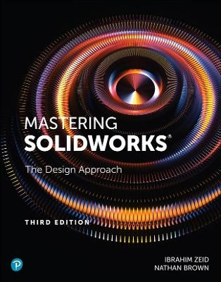
Mastering SolidWorks
Peachpit Press Publications (Verlag)
978-0-13-688726-3 (ISBN)
Fully updated for SolidWorks 2021, Mastering SolidWorks, Third Edition, thoroughly illuminates solid modeling CAD techniques for developing parts, assemblies, and drawings. Additional specializations, SolidWorks toolboxes, and manufacturing techniques are also covered, including sheet metal, injection molding, and animation. New illustrations reflect SolidWorks 2021 throughout, and this edition fully reflects changes in workflow since SolidWorks 2014.
Mastering SolidWorks can develop CAD skills in students with little or no solid modeling expertise, help more advanced students hone specialized skills, and prepare any SolidWorks user for SolidWorks Associate (CSWA) or Professional (CSWP) certification. Written especially for beginners and intermediate users, it will also be valuable to experienced users requiring specialized knowledge, to companies training their own professionals, and to all schools teaching engineering, design, or 3D modeling.
Understand SolidWorks as a powerful design/manufacturing system, not just a piece of software
Learn key modeling concepts for working efficiently, avoiding errors, and transferring your skills anywhere
Rapidly create, assemble, document, and visualize parts
Embed “design intelligence” to make parts easier to edit and manufacture
Master part modeling: from basic features, drawings, and assemblies to advanced curves, surfaces, and sustainable designs
Develop and analyze parts using tolerances and SolidWorks analysis tools
Manufacture parts with rapid prototyping, numerical control machining, and injection molding
Ibrahim Zeid, Professor of Mechanical, Industrial and Manufacturing Engineering at Northeastern University, is a Fellow of the American Society of Mechanical Engineers. His research focuses on mechanics, personalized medicine, simulation, and complex networks analysis. His honors include Northeastern's Excellence in Teaching Award and SAE's Ralph R. Teetor National Educational Award. Nathan Brown, research engineer and instructor in the Department of Bioengineering at the University of Louisville, teaches SolidWorks, 3D modeling, and manufacturing processes at the graduate level. A Certified SolidWorks Associate, his extensive CAD experience includes developing custom, anatomically accurate pelvic limb 3D computer models to investigate and correct ligament injuries and deficiencies in dogs.
Preface vi
PART I: COMPUTER-AIDED DESIGN (CAD) BASICS 1
Chapter 1 Getting Started 3
1.1 Introduction 3
1.2 Engineering Design Process 4
1.3 CAD Process 4
1.4 Manufacturing Process 5
1.5 CAM Process 6
1.6 SolidWorks Installation and Resources 6
1.7 SolidWorks Overview 8
1.8 Customize SolidWorks 11
1.9 Modeling Plan 12
1.10 Part Creation 14
1.11 Examples 15
1.12 Tutorials 22
Tutorial 1-1 Create a Flap 22
Tutorial 1-2 Create a Pin and Bushing Bearing 24
Tutorial 1-3 Create a Pillow Block 25
Tutorial 1-4 Create Drawings 28
Tutorial 1-5 Create an Assembly 29
Problems 32
Chapter 2 Modeling Management 37
2.1 Overview 37
2.2 Types of CAD Models 37
2.3 Planning Part Creation 39
2.4 Part Topology 40
2.5 Parametric Modeling 40
2.6 Customizing SolidWorks 42
2.7 Productivity Tools 43
2.8 Coordinate Systems 43
2.9 Sketch Planes 44
2.10 Sketch Status 46
2.11 Part Feature Tree 47
2.12 Construction Geometry 48
2.13 Reference Geometry 48
2.14 Sketch Entities 50
2.15 Sketch Relations 51
2.16 Equations and Link Values 51
2.17 Geometric Modifiers 53
2.18 Grids 54
2.19 Patterns 54
2.20 Selecting, Editing, and Measuring Entities 58
2.21 Boolean Operations 59
2.22 Templates 61
2.23 Viewing 61
2.24 Model Communication 62
2.25 Tutorials 63
Tutorial 2-1 Create a Coil Spring 63
Tutorial 2-2 Create a Mount Plate 65
Tutorial 2-3 Create a Bracket 66
Tutorial 2-4 Create a Wheel 67
Tutorial 2-5 Create a Tire and a Pin 69
Tutorial 2-6 Create a Caster Assembly 70
Problems 73
Chapter 3 Design Intent 81
3.1 Introduction 81
3.2 Capturing Design Intent 82
3.3 Documenting Design Intent 83
3.4 Comments 83
3.5 Design Binder 84
3.6 Equations 85
3.7 Design Tables and Configurations 85
3.8 Dimension Names 85
3.9 Feature Names 85
3.10 Folders 86
3.11 Tutorials 86
Tutorial 3-1 Design Intent via Two Modeling Plans 86
Tutorial 3-2 Design Intent via Three Modeling Plans 89
Tutorial 3-3 Design Intent via Design Specifications 91
Tutorial 3-4 Design Intent via Mating Conditions 93
Problems 95
PART II: BASIC PART MODELING 97
Chapter 4 Features and Macros 99
4.1 Introduction 99
4.2 Features 100
4.3 Spur Gears 103
4.4 Design Library and Library Features 109
4.5 Configurations and Design Tables 110
4.6 Macros 111
4.7 Tutorials 114
Tutorial 4-1 Create Sweep Features 114
Tutorial 4-2 Create Loft Features 116
Tutorial 4-3 Use the Hole Wizard 118
Tutorial 4-4 Create Compression Spring 119
Tutorial 4-5 Create Spiral 120
Tutorial 4-6 Create Features 121
Tutorial 4-7 Use the Smart Fasteners Wizard 122
Tutorial 4-8 Create a Bolt 123
Problems 126
Chapter 5 Drawings 135
5.1 Introduction 135
5.2 Engineering Drafting and Graphics Communication 136
5.3 ASME Abbreviation Rules 137
5.4 ASME Drafting Rules 138
5.5 ASME Dimensioning Rules 139
5.6 Dimensions 142
5.7 Drawing Content and Layout 144
5.8 Angles of Projection 145
5.9 Views 146
5.10 Sheets 148
5.11 Title Blocks 149
5.12 Drafting Control 150
5.13 Tolerances 150
5.14 Bills of Materials 151
5.15 Model and Drawing Associativity 151
5.16 Design Checker 151
5.17 Tutorials 152
Tutorial 5-1 Create Drawing Views 152
Tutorial 5-2 Insert Annotations 153
Tutorial 5-3 Fill Title Block 153
Tutorial 5-4 Create Assembly Drawing with Bill of Materials 154
Tutorial 5-5 Use Model-Drawing Associativity 155
Problems 156
Chapter 6 Assemblies 157
6.1 Introduction 157
6.2 Assembly Mates 158
6.3 Bottom-Up Assembly Modeling 159
6.4 Top-Down Assembly Modeling 159
6.5 The Assembly Tree 164
6.6 Assembly Drawings 164
6.7 Assembly Exploded Views and Animations 164
6.8 Assembly Motion Study 165
6.9 Interference and Collision Detections 166
6.10 Assembly Design Tables 166
6.11 Tutorials 166
Tutorial 6-1 Create a Cam and a Follower Assembly 167
Tutorial 6-2 Create a Working Hinge Assembly 168
Tutorial 6-3 Mate Two Gears with a Gear Mate 169
Tutorial 6-4 Create a Functional Rack and Pinion 171
Tutorial 6-5 Create a Functional Ball Screw 173
Tutorial 6-6 Study Universal Joint Motion 174
Tutorial 6-7 Create a Motion Study 176
Tutorial 6-8 Detect Collision and Interference 178
Tutorial 6-9 Create a Design Table 179
Tutorial 6-10 Create a Part in the Context of an Assembly 180
Problems 183
Chapter 7 Rendering and Animation 195
7.1 Introduction 195
7.2 Scenes and Lighting 196
7.3 Rendering Models 197
7.4 Decals 198
7.5 Textures 199
7.6 Materials 199
7.7 Appearance and Transparency 201
7.8 Background and Scenes 201
7.9 Cameras and Camera Sleds 201
7.10 Animation 201
7.11 Tutorials 202
Tutorial 7-1 Apply Colors to Objects 202
Tutorial 7-2 Apply a Background and a Scene 203
Tutorial 7-3 Apply Lights to a Scene 204
Tutorial 7-4 Add Material and Transparency 205
Tutorial 7-5 Add a Camera to a Scene 206
Tutorial 7-6 Create a Motion Study 207
Tutorial 7-7 Create a Camera-Sled Based
Animation 210
Problems 213
PART III: ADVANCED PART MODELING 215
Chapter 8 Curves 217
8.1 Introduction 217
8.2 Curve Representation 218
8.3 Line Parametric Equation 219
8.4 Circle Parametric Equation 220
8.5 Spline Parametric Equation 221
8.6 Two-Dimensional Curves 222
8.7 Three-Dimensional Curves 223
8.8 Curve Management 224
8.9 Tutorials 224
Tutorial 8-1 Create a 2D Curve by Using an Explicit Equation 224
Tutorial 8-2 Create a 2D Curve by Using a Parametric Equation 225
Tutorial 8-3 Create a 3D Curve by Using a Parametric Equation 225
Tutorial 8-4 Create a 3D Curve by Using 3D Points 227
Tutorial 8-5 Create a 3D Curve by Using 3D Sketching 228
Tutorial 8-6 Create a 3D Curve by Using Composite Curves 229
Tutorial 8-7 Create a 3D Curve by Projecting a Sketch onto a Curved Face 231
Tutorial 8-8 Create a 3D Curve Using Projected Curves 232
Tutorial 8-9 Create a Stethoscope Model 241
Problems 244
Chapter 9 Surfaces 249
9.1 Introduction 249
9.2 Surfaces 249
9.3 Using Surfaces in Solid Modeling 252
9.4 Surface Representation 254
9.5 Plane Parametric Equation 255
9.6 Ruled Surface Parametric Equation 257
9.7 Surface Visualization 260
9.8 Surface Management 260
9.9 Tutorials 261
Tutorial 9-1 Create Basic Surfaces: Extrude, Revolve, Loft, Sweep, Knit, and Radiate 261
Tutorial 9-2 Create Basic Surfaces: Planar, Filled, Boundary, and Offset 263
Tutorial 9-3 Visualize Surfaces 264
Tutorial 9-4 Create an Artistic Bowl 265
Tutorial 9-5 Use Surface Intersections 268
Tutorial 9-6 Create a Tablespoon 269
Tutorial 9-7 Create a Computer Mouse 271
Tutorial 9-8 Create a Baseball Hat 273
Tutorial 9-9 Create a Hair Dryer 277
Tutorial 9-10 Create an Oil Container 279
Problems 282
Chapter 10 Sheet Metal and Weldments 289
10.1 Introduction 289
10.2 Sheet Metal 289
10.3 Sheet Metal Features 291
10.4 Sheet Metal FeatureManager Design Tree 296
10.5 Sheet Metal Methods 297
10.6 Weldments 299
10.7 Weldment Features 301
10.8 Weld Symbols 305
10.9 Tutorials 306
Tutorial 10-1 Create Sheet Metal 306
Tutorial 10-2 Create a Sheet Metal Drawing 308
Tutorial 10-3 Create a Sheet Metal Part from a Solid Body 309
Tutorial 10-4 Create a Sheet Metal Part from a Flattened State 310
Tutorial 10-5 Create a Weldment 311
Tutorial 10-6 Create a Weldment Drawing 313
Problems 316
Chapter 11 Sustainable Design 319
11.1 Introduction 319
11.2 Design and Society 321
11.3 Guidelines and Principles 321
11.4 Life Cycle Assessment 323
11.5 Impact Metric 325
11.6 Implementation 327
11.7 Design Activities 327
11.8 Sustainable Design Tools 328
11.9 SolidWorks Sustainability 329
11.10 Tutorials 332
Tutorial 11-1 Redesign a Steel Washer 332
Problems 335
PART IV: PART DEVELOPMENT AND ANALYSIS 337
Chapter 1 2 Tolerances 339
12.1 Introduction 339
12.2 Tolerance Types 340
12.3 Tolerance Concepts 340
12.4 ASME Tolerance Rules 343
12.5 Tolerancing Tapers 347
12.6 Limits of Dimensions 348
12.7 Tolerance Accumulation 353
12.8 Statistical Tolerancing 354
12.9 True Position 356
12.10 Geometric Tolerances 357
12.11 Datum Target Symbols 359
12.12 Tolerance Interpretation 360
12.13 Tolerance Analysis 362
12.14 SolidWorks Tolerance Analysis 364
12.15 Tutorials 367
Tutorial 12-1 Create Conventional Tolerances 367
Tutorial 12-2 Create Geometric Tolerances 369
Tutorial 12-3 Define Datum Targets 370
Tutorial 12-4 Tolerance a Taper 371
Tutorial 12-5 Perform Tolerance Stack-up Analysis 372
Problems 374
Chapter 13 Analysis Tools 377
13.1 Introduction 377
13.2 Data Exchange 378
13.3 Mass Properties 381
13.4 Animation and Motion Analysis 385
13.5 Flow Simulation 386
13.6 Finite Element Method 386
13.7 Finite Element Analysis 389
13.8 SolidWorks Simulation 391
13.9 Von Mises Stress 391
13.10 Tutorials 396
Tutorial 13-1 Export Native SolidWorks Files 396
Tutorial 13-2 Import IGES and STEP Files into SolidWorks 396
Tutorial 13-3 Calculate Mass Properties of a Solid 397
Tutorial 13-4 Perform Motion Analysis Using a Motor 398
Tutorial 13-5 Perform Static Linear FEA on a Part 403
Tutorial 13-6 Perform Thermal FEA on a Part 405
Tutorial 13-7 Perform Flow Analysis on a Hose 406
Problems 408
PART V: PART MANUFACTURING 409
Chapter 14 Rapid Prototyping 411
14.1 Introduction 411
14.2 RP Applications 412
14.3 RP Overview 414
14.4 RP Concepts 414
14.5 SolidWorks Triangulation 417
14.6 RP Steps 418
14.7 RP Building Techniques 419
14.8 Bottle Prototype 420
14.9 Tutorials 421
Tutorial 14-1 Generate Part Prototype File 421
Tutorial 14-2 Generate Assembly Prototype File 422
Tutorial 14-3 Read Back an STL File 423
Problems 425
Chapter 15 Numerical Control Machining 427
15.1 Introduction 427
15.2 Basics of Machine Tools 428
15.3 Basics of Machining 430
15.4 Turning 438
15.5 Drilling 438
15.6 Milling 439
15.7 Electrical Discharge Machining 439
15.8 Manufacturing of Design 441
15.9 SolidWorks DFMXpress 442
15.10 Basics of NC Machining 445
15.11 G-Code and M-Code Programming 447
15.12 CAM Add-In Software 449
15.13 Tutorials 449
Tutorial 15-1 Drill Holes 450
Tutorial 15-2 Mill Faces 452
Tutorial 15-3 Mill Pockets 455
Tutorial 15-4 Mill Slots 457
Problems 460
Chapter 16 Injection Molding 463
16.1 Introduction 463
16.2 Basics of Injection Molding Machines 464
16.3 Basics of Injection Molding 465
16.4 Basics of Mold Design 467
16.5 Basics of Part Design 470
16.6 Phases of Mold Design 471
16.7 SolidWorks Mold Design 472
16.8 Tutorials 473
Tutorial 16-1 Create a Block Mold 473
Tutorial 16-2 Create a Sandbox Mold 477
Tutorial 16-3 Create a Hemisphere Mold 481
Tutorial 16-4 Create an Easter Egg Mold 484
Tutorial 16-5 Generate a Mold Drawing 487
Problems 488
Appendix A ANSI and ISO Tolerance Tables 491
Appendix B SolidWorks Certification 505
B.1 Certified SolidWorks Associate (CSWA) 505
B.2 Certified SolidWorks Professional (CSWP) 506
B.3 CSWP-Surfacing 506
B.4 CSWP-Sheet Metal 507
B.5 CSWP-Weldments 507
B.6 CSWP-Simulation 507
B.7 CSWP-Mold Making 508
B.8 Testing Resources 508
B.9 Sample Test Questions 509
Index 517
| Erscheinungsdatum | 07.05.2021 |
|---|---|
| Verlagsort | Berkeley |
| Sprache | englisch |
| Maße | 218 x 272 mm |
| Gewicht | 1160 g |
| Themenwelt | Informatik ► Weitere Themen ► CAD-Programme |
| Technik ► Maschinenbau | |
| ISBN-10 | 0-13-688726-0 / 0136887260 |
| ISBN-13 | 978-0-13-688726-3 / 9780136887263 |
| Zustand | Neuware |
| Informationen gemäß Produktsicherheitsverordnung (GPSR) | |
| Haben Sie eine Frage zum Produkt? |
aus dem Bereich


