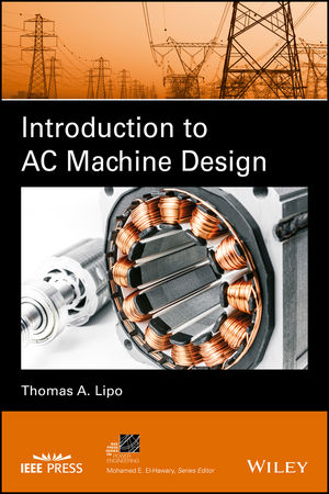
Introduction to AC Machine Design
Wiley-IEEE Press (Verlag)
978-1-119-35216-7 (ISBN)
The only book on the market that emphasizes machine design beyond the basic principles of AC and DC machine behavior
AC electrical machine design is a key skill set for developing competitive electric motors and generators for applications in industry, aerospace, and defense. This book presents a thorough treatment of AC machine design, starting from basic electromagnetic principles and continuing through the various design aspects of an induction machine. Introduction to AC Machine Design includes one chapter each on the design of permanent magnet machines, synchronous machines, and thermal design. It also offers a basic treatment of the use of finite elements to compute the magnetic field within a machine without interfering with the initial comprehension of the core subject matter.
Based on the author’s notes, as well as after years of classroom instruction, Introduction to AC Machine Design:
Brings to light more advanced principles of machine design—not just the basic principles of AC and DC machine behavior
Introduces electrical machine design to neophytes while also being a resource for experienced designers
Fully examines AC machine design, beginning with basic electromagnetic principles
Covers the many facets of the induction machine design
Introduction to AC Machine Design is an important text for graduate school students studying the design of electrical machinery, and it will be of great interest to manufacturers of electrical machinery.
THOMAS A. LIPO, PhD is an Emeritus Professor at the University of Wisconsin-Madison and also a Research Professor at Florida State University. He has published over 700 technical papers as well as 52 patents, 5 books, and 8 book chapters. Dr. Lipo is a Life Fellow of IEEE, and recipient of the IEEE Medal in Power Engineering. He previously co-published Pulse Width Modulation for Power Converters: Principles and Practice with Wiley-IEEE Press.
Preface and Acknowledgments xiii
List of Principal Symbols xv
About the Author xxiii
Chapter 1 Magnetic Circuits 1
1.1 Biot–Savart Law 1
1.2 The Magnetic Field B 2
1.3 Example—Computation of Flux Density B 3
1.4 The Magnetic Vector Potential A 5
1.5 Example—Calculation of Magnetic Field from the Magnetic Vector Potential 6
1.6 Concept of Magnetic Flux 7
1.7 The Electric Field E 9
1.8 Ampere’s Law 10
1.9 Magnetic Field Intensity H 12
1.10 Boundary Conditions for B and H 15
1.11 Faraday’s Law 17
1.12 Induced Electric Field Due to Motion 18
1.13 Permeance, Reluctance, and the Magnetic Circuit 19
1.14 Example—Square Toroid 23
1.15 Multiple Circuit Paths 23
1.16 General Expression for Reluctance 24
1.17 Inductance 27
1.18 Example—Internal Inductance of a Wire Segment 28
1.19 Magnetic Field Energy 29
1.20 The Problem of Units 31
1.21 Magnetic Paths Wholly in Iron 33
1.22 Magnetic Materials 35
1.23 Example—Transformer Structure 37
1.24 Magnetic Circuits with Air Gaps 40
1.25 Example—Magnetic Structure with Saturation 42
1.26 Example—Calculation for Series–Parallel Iron Paths 43
1.27 Multiple Winding Magnetic Circuits 44
1.28 Magnetic Circuits Applied to Electrical Machines 46
1.29 Effect of Excitation Coil Placement 48
1.30 Conclusion 50
Reference 50
Chapter 2 The MMF and Field Distribution of an AC Winding 51
2.1 MMF and Field Distribution of a Full-Pitch Winding for a Two Pole Machine 51
2.2 Fractional Pitch Winding for a Two-Pole Machine 54
2.3 Distributed Windings 56
2.4 Concentric Windings 62
2.5 Effect of Slot Openings 64
2.6 Fractional Slot Windings 67
2.7 Winding Skew 70
2.8 Pole Pairs and Circuits Greater than One 73
2.9 MMF Distribution for Three-Phase Windings 73
2.10 Concept of an Equivalent Two-Phase Machine 76
2.11 Conclusion 77
References 77
Chapter 3 Main Flux Path Calculations Using Magnetic Circuits 79
3.1 The Main Magnetic Circuit of an Induction Machine 79
3.2 The Effective Gap and Carter’s Coefficient 80
3.3 The Effective Length 84
3.4 Calculation of Tooth Reluctance 86
3.5 Example 1—Tooth MMF Drop 89
3.6 Calculation of Core Reluctance 94
3.7 Example 2—MMF Drop Over Main Magnetic Circuit 102
3.8 Magnetic Equivalent Circuit 111
3.9 Flux Distribution in Highly Saturated Machines 112
3.10 Calculation of Magnetizing Reactance 116
3.11 Example 3—Calculation of Magnetizing Inductance 120
3.12 Conclusion 123
References 124
Chapter 4 Use of Magnetic Circuits in Leakage Reactance Calculations 125
4.1 Components of Leakage Flux in Induction Machines 125
4.2 Specific Permeance 127
4.3 Slot Leakage Permeance Calculations 129
4.4 Slot Leakage Inductance of a Single-Layer Winding 134
4.5 Slot Leakage Permeance of Two-Layer Windings 135
4.6 Slot Leakage Inductances of a Double-Cage Winding 137
4.7 Slot Leakage Inductance of a Double-Layer Winding 139
4.8 End-Winding Leakage Inductance 144
4.8.1 Method of Images 144
4.8.2 End-Winding Leakage Inductance of Random-Wound Coils 147
4.8.3 End-Winding Leakage Inductance of a Coil with Stator Iron Treated as a Perfect Conductor 148
4.8.4 End-Winding Leakage Inductance of a Coil with Stator Iron Treated as Air 150
4.8.5 End-Winding Leakage Inductance per Phase 153
4.8.6 End-Winding Leakage of Form-Wound Coils 153
4.8.7 Squirrel-Cage End-Winding Inductance 155
4.9 Stator Harmonic or Belt Leakage 156
4.10 Zigzag Leakage Inductance 159
4.11 Example 4—Calculation of Leakage Inductances 164
4.12 Effective Resistance and Inductance Per Phase of Squirrel-Cage Rotor 171
4.13 Fundamental Component of Rotor Air Gap MMF 175
4.14 Rotor Harmonic Leakage Inductance 177
4.15 Calculation of Mutual Inductances 181
4.16 Example 5—Calculation of Rotor Leakage Inductance Per Phase 186
4.17 Skew Leakage Inductance 187
4.18 Example 6—Calculation of Skew Leakage Effects 189
4.19 Conclusion 190
References 190
Chapter 5 Calculation of Induction Machine Losses 193
5.1 Introduction 193
5.2 Eddy Current Effects in Conductors 194
5.3 Calculation of Stator Resistance 203
5.4 Example 7—Calculation of Stator and Rotor Resistance 205
5.5 Rotor Parameters of Irregularly Shaped Bars 212
5.6 Categories of Electrical Steels 216
5.7 Core Losses Due to Fundamental Flux Component 217
5.8 Stray Load and No-Load Losses 222
5.9 Calculation of Surface Iron Losses Due to Stator Slotting 228
5.10 Calculation of Tooth Pulsation Iron Losses 237
5.11 Friction and Windage Losses 244
5.12 Example 8—Calculation of Iron Loss Resistances 244
5.13 Conclusion 250
References 250
Chapter 6 Principles of Design 251
6.1 Design Factors 251
6.2 Standards for Machine Construction 252
6.3 Main Design Features 255
6.4 The D2L Output Coefficient 258
6.4.1 Essen’s Rule 259
6.4.2 Magnetic Shear Stress 261
6.4.3 The Aspect Ratio 265
6.4.4 Base Impedance 268
6.5 The D3L Output Coefficient 269
6.6 Power Loss Density 277
6.7 The D2.5L Sizing Equation 277
6.8 Choice of Magnetic Loading 278
6.8.1 Maximum Flux Density in Iron 279
6.8.2 Magnetizing Current 280
6.9 Choice of Electric Loading 281
6.9.1 Voltage Rating 281
6.9.2 Current Density Constraints 282
6.9.3 Representative Values of Current Density 285
6.10 Practical Considerations Concerning Stator Construction 287
6.10.1 Random Wound vs. Formed Coil Windings 288
6.10.2 Delta vs. Wye Connection 289
6.10.3 Lamination Insulation 290
6.10.4 Selection of Stator Slot Number 290
6.10.5 Choice of Dimensions of Active Material for NEMA Designs 291
6.10.6 Selection of Wire Size 292
6.10.7 Selection of Air Gap 293
6.11 Rotor Construction 293
6.11.1 Slot Combinations to Avoid 294
6.11.2 Rotor Heating During Starting or Under Stalled Conditions 294
6.12 The Design Process 295
6.13 Effect of Machine Performance by a Change in Dimension 299
6.14 Conclusion 302
References 302
Chapter 7 Thermal Design 305
7.1 The Thermal Problem 305
7.2 Temperature Limits and Maximum Temperature Rise 306
7.3 Heat Conduction 307
7.3.1 Simple Heat Conduction Through a Rectangular Plate 308
7.3.2 Heat Conduction Through a Cylinder 309
7.3.3 Heat Conduction with Simple Internal Heat Generation 311
7.3.4 Example 9—Stator Winding Heating 313
7.3.5 One-Dimensional Conductive Heat Flow with Distributed Internal Heat Generation 314
7.3.6 Two- and Three-Dimensional Conductive Heat Flow with Internal Distributed Heat Generation 316
7.3.7 Application of Two-Dimensional Heat Flow to Stator Teeth 317
7.3.8 Radial Heat Flow Over Solid Cylinder with Internal Heat Generation 318
7.3.9 Heat Flow Over Cylindrical Shell with Internal Distributed Heat Generation 320
7.4 Heat Convection on Plane Surfaces 325
7.5 Heat Flow Across the Air Gap 327
7.6 Heat Transfer by Radiation 328
7.7 Cooling Methods and Systems 329
7.7.1 Surface Cooling by Air 329
7.7.2 Internal Cooling 329
7.7.3 Cooling in a Circulatory System 329
7.7.4 Cooling with Liquids 330
7.7.5 Direct Gas Cooling 330
7.7.6 Gas as a Cooling Medium 331
7.7.7 Liquids as a Cooling Medium 332
7.8 Thermal Equivalent Circuit 333
7.9 Example 10—Heat Distribution of 250 HP Induction Machine 338
7.9.1 Heat Inputs 339
7.9.2 Thermal Resistances 342
7.10 Transient Heat Flow 353
7.10.1 Externally Generated Heat 353
7.10.2 Internally Generated Heat—Stalled Operation 354
7.10.3 Thermal Instability 356
7.11 Conclusion 357
References 357
Chapter 8 Permanent Magnet Machines 359
8.1 Magnet Characteristics 359
8.2 Hysteresis 362
8.3 Permanent Magnet Materials 364
8.4 Determination of Magnet Operating Point 366
8.5 Sinusoidally FED Surface PM Motor 369
8.6 Flux Density Constraints 373
8.7 Current Density Constraints 376
8.8 Choice of Aspect Ratio 377
8.9 Eddy Current Iron Losses 377
8.9.1 Eddy Current Tooth Iron Losses 378
8.9.2 Eddy Current Yoke Iron Losses 379
8.10 Equivalent Circuit Parameters 380
8.10.1 Magnetizing Inductance 381
8.10.2 Current Source 382
8.10.3 Eddy Current Iron Loss Resistance 382
8.10.4 Alternate Equivalent Circuit 383
8.11 Temperature Constraints and Cooling Capability 383
8.12 Magnet Protection 384
8.12.1 Magnet Protection for Maximum Steady-State Current 384
8.12.2 Magnet Protection for Transient Conditions 386
8.13 Design for Flux Weakening 387
8.14 PM Motor with Inset Magnets 389
8.14.1 Short-Circuit Protection 392
8.14.2 Flux Weakening 392
8.15 Cogging Torque 393
8.16 Ripple Torque 394
8.17 Design Using Ferrite Magnets 394
8.18 Permanent Machines with Buried Magnets 395
8.18.1 PM Machines with Buried Circumferential Magnets 396
8.19 Conclusion 399
Acknowledgment 400
References 400
Chapter 9 Electromagnetic Design of Synchronous Machines 401
9.1 Calculation of Useful Flux Per Pole 401
9.2 Calculation of Direct and Quadrature Axis Magnetizing Inductance 402
9.3 Determination of Field Magnetizing Inductance 411
9.4 Determination of d-Axis Mutual Inductances 418
9.5 Calculation of Rotor Pole Leakage Permeances 420
9.6 Stator Leakage Inductances of a Salient Pole Synchronous Machine 424
9.6.1 Zigzag or Tooth-Top Leakage Inductance of Salient Pole Machines 424
9.7 The Amortisseur Winding Parameters 428
9.8 Mutual and Magnetizing Inductances of the Amortisseur Winding 435
9.9 Direct Axis Equivalent Circuit 435
9.10 Referral of Rotor Parameters to the Stator 438
9.11 Quadrature Axis Circuit 441
9.12 Power and Torque Expressions 446
9.13 Magnetic Shear Stress 449
9.14 Field Current Profile 451
9.15 Conclusion 453
References 453
Chapter 10 Finite-Element Solution of Magnetic Circuits 455
10.1 Formulation of the Two-Dimensional Magnetic Field Problem 455
10.2 Significance of the Vector Potential 458
10.3 The Variational Method 459
10.4 Nonlinear Functional and Conditions for Minimization 460
10.5 Description of the Finite-Element Method 465
10.6 Magnetic Induction and Reluctivity in the Triangle Element 467
10.7 Functional Minimization 468
10.8 Formulation of the Stiffness Matrix Equation 472
10.9 Consideration of Boundary Conditions 474
10.10 Step-By-Step Procedure for Solving the Finite-Element Problem 476
10.11 Finite-Element Modeling of Permanent Magnets 482
10.12 Conclusion 485
10.A Appendix 486
References 487
Appendix A Computation of Bar Current 489
Appendix B FEM Example 493
Index 505
| Erscheinungsdatum | 30.01.2018 |
|---|---|
| Reihe/Serie | IEEE Press Series on Power and Energy Systems |
| Sprache | englisch |
| Maße | 155 x 236 mm |
| Gewicht | 907 g |
| Themenwelt | Technik ► Elektrotechnik / Energietechnik |
| Technik ► Nachrichtentechnik | |
| ISBN-10 | 1-119-35216-9 / 1119352169 |
| ISBN-13 | 978-1-119-35216-7 / 9781119352167 |
| Zustand | Neuware |
| Informationen gemäß Produktsicherheitsverordnung (GPSR) | |
| Haben Sie eine Frage zum Produkt? |
aus dem Bereich


