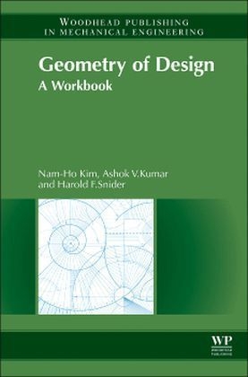
Geometry of Design
Woodhead Publishing Ltd (Verlag)
978-1-78242-173-3 (ISBN)
- Keine Verlagsinformationen verfügbar
- Artikel merken
Nam-Ho Kim is an Associate Professor in the Department of Mechanical and Aerospace Engineering, College of Engineering, University of Florida, USA. Harold F. Snider is a Senior Lecturer in the Department of Mechanical and Aerospace Engineering, College of Engineering, University of Florida, USA.
Preface
Chapter 1: Basic Engineering Drawing Definitions and Practices
A1.0a Introduction
A1.1a Drawing Instruments
A1.1b Uppercase Vertical Lettering
A1.2a Isometric & Oblique Views
A1.2b Pictorial Sketching Exercises
A1.2 Isometric Sketching
A1.3 Oblique Sketching
A1.4a Elements of a Working Drawing
A1.4b Views, Conventions… …and Projection Systems
A1.4c Guide Block
A1.4 Six Orthographic Views of Guide Block
C1.1a Drawing Views, Formats, Notes
C1.1b Drawing Setup Variables
C1.1c Proe Commands and other Drawing Options
Chapter 2: Views Perspective and Sectional
A2.0a Introduction
A2.1a 1, 2 and 3–point Perspective
A2.1b Internal Perspective
A2.1 2-Point Perspective
A2.2 Visualization: Orthographic, Isometric
C2.1a Orthographic Views,Show and Erase and Other Drawing Options
Chapter 3: Geometric Construction
A3.0a Introduction
A3.1a Geometric Constructions
A3.1b Other Geometric Constructions
A3.1 Clamp Ring: Geometric Cons
A3.2a Sections and Symbols
A3.2b Sections and Concentions …Examples…
A3.2c Sections and Concentions …Examples…
A3.2 Sections: Offset, Broken-Out
A3.3 Sections: Half, Revolved
C3.1a Clamp Ring: Constraints
C3.1hist Design Intent History
L3.1a CLAMP RING; Constraints
Z3.1a CLAMP RING; Constraints
Chapter 4: 3-View Projection System Drawing: Design Intent
A4.0a Introduction
A4.1a 3-View Projection System and Rules of Visibility
A4.1 Visibility
A4.2a AUXILIARY PROJECTION Multi–Sided Projection boxes
A4.2 Auxiliary Views
A4.3a Multiple Auxiliary Views Example
A4.3 Multiple Aux Views
C4.1a SHAFT SUPPORT …Extrude feature
C4.1b Design Intent
C4.1hist Design Intent History
L4.1a CHANNEL GUIDE …Extrude feature
Z4.1a CHANNEL GUIDE …Extrude feature
Chapter 5: Descriptive Geometry 1
A5.0a Introduction
A5.1a Fundamental Constructions of Descriptive Geometry
A5.1b Fundamental Constructions of Descriptive Geometry
A5.1c Signature of Principal Lines and Planes
A5.1 Points and Lines: Classify, Slope & Bearing
A5.2 Lines: Parallel, Intersect, Skew, Identify Planes
A5.3 TL and PV of a line
A5.4a Viewpoints and Direction Vectors
A5.4 Viewpoints Direction Vectors
A5.5a DIHEDRAL ANGLE example
C5.1a SHAFT: Revolve feature
C5.1hist Design Intent History
L5.1a SHAFT… …Revolve feature
Z5.1a SHAFT; Revolve
Chapter 6: Descriptive Geometry 2
A6.0a Introduction
A6.1 EV and TS of a Plane
A6.2 Angle Between a Line and a Plane
A6.3 Bearing, Strike and Dip
A6.4a Sheet Metal Vocabulary
A6.4b Sheet Metal Example
A6.4c Sheet Metal Operations
C6.1a SWITCH COVER …Shell and Pattern functions
C6.1hist Design Intent History
L6.1a SWITCH COVER …Shell and Pattern functions
Z6.1a BEARING SUPPORT …Shell and Pattern functions
Chapter 7: Descriptive Geometry 3
A7.0a Introduction
A7.1a The CUTTING PLANE
A7.1 INTERSECTION of LINE and PLANE
J7.1 INTERSECTION of LINE and PLANE
X7.1 INTERSECTION of LINE and PLANE
A7.2 Intersection of two planes: pierce point
C7.1a SUNDIAL…PV, TL, EV, TS, Area… …and DIHEDRAL Angle
C7.1hist Design Intent History
L7.1a SUNDAL…PV, TL, EV, TS, Area… …and DIHEDRAL Angle
Z7.1a SUNDIAL…PV, TL, EV, TS, Area… …and DIHEDRAL Angle
Chapter 8: Parallelism and Perpendicularity
A8.0a Introduction
A8.1 Parallelism
A8.2 Perpendicular Lines
Chapter 9: Mutual Perpendicular: Assembly End Clearance
A9.0a Introduction
A9.1 Mutual Perpendicular
A9.2a Mixer Assembly: end Clearance
A9.2 Assembly end Clearance
C9.1a SPRAY NOZZLE: Sweep, Blend Features
C9.2a MUTUAL PERPENDICULAR Axial Clearance
C9.1hist Design Intent History
Chapter 10: Dimensioning and Tolerances: Assemblies
A10.0a Introduction
A10.1a Dimensioning Terms
A10.1b Dimensioning Guidelines
A10.1c Dimensioning Guidelines
A10.1d Methods of Tolerancing
A10.1e Dimensioning… Symmetric…Asym metric
A10.1 Dimensioning
A10.2a Design of Fits Hole Basis and Shaft Basis
A10.2 Design of Fits
A10.3a Clearances, (ANSI) Tolerances and Fits
A10.3b Clearances, (Metric) Tolerances and Fits
A10.3 ANSI fits, ISO fits
C10.1a Mixer Assembly… C 101XA01. asm Mixer Assembly Drawing…C101X01.drw
C10.1b …Bill of Materials…Balloons … …Assembly Sections… …Exploded Views…
C10.1 hist Design Intent History
Chapter 11: Assembly Line Design
A11.0a Introduction
A11.1a Thread Data Allowances and Tolerances
A11.1 Screw Assembly Design Problem
A11.2a Working Drawingsand Specifications
A11.2b Working Drawings and Specifications
A11 2c Assembly Line for Low Volume Production
A11.2d Assembly Line for Low Volume Production
A11.2e Bench Assembly Line
A11.2f Assembly Line Operations
C11.1a Assembly Line Layout
Chapter 12: Threads and Fasteners
A12.0a Introduction
A12.1a ANSI Thread Notes
A12.1b Screw Thread Representation
A12.1c MetricThread Notes
A12.1 Screw thread terminology
A12.2 Thread notes
A12.3a Rivets and other Standard Hardware
A12.4a Geometric Tolerancing
A12.4 GDT Feature Control Frames
C12.1a CONICAL COMPRESSION SPRING
C12.1 hist Title: Conical Spring; C 121 X01 hist.pdf Part No.: C 121 X0 1.prt
Chapter 13: Surface Development
A13.0a Introduction
A13.1a Finding TL by Revolution
A13.1 Surface Development
C13.1a ARCH… …Swept Blend Feature; Equation Editor
C13.1hist Design Intent History
L13.1a ARCH Swept Blend Feature; Equation Editor
C13.2a VORTEX ASSEMBLY …Surface Modeling …Convert Surfaces to Solids
C13.2hist Design Intent History
L13.2a VORTEX ASSEMBLY…Surface Modeling …convert Surfaces to Solids
| Erscheint lt. Verlag | 2.1.2015 |
|---|---|
| Verlagsort | Cambridge |
| Sprache | englisch |
| Maße | 156 x 234 mm |
| Gewicht | 1310 g |
| Themenwelt | Informatik ► Weitere Themen ► CAD-Programme |
| Technik ► Maschinenbau | |
| ISBN-10 | 1-78242-173-4 / 1782421734 |
| ISBN-13 | 978-1-78242-173-3 / 9781782421733 |
| Zustand | Neuware |
| Informationen gemäß Produktsicherheitsverordnung (GPSR) | |
| Haben Sie eine Frage zum Produkt? |
aus dem Bereich


